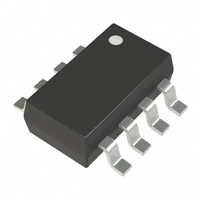
Dual-channel high-side switch with controlled turn-on
It handles up to 500 mA per output across a 1.62 V to 5.5 V load voltage range, with a typical on-resistance of 342 mOhm per channel. The part integrates slew-rate control to limit inrush current during turn-on, plus a load-discharge circuit that pulls the output to ground when the switch is disabled. These features make it a direct fit for sequenced power-rail management in portable and industrial designs.
At 500 mA per channel, the 342 mOhm typical on-resistance produces about 85 mV of voltage drop and 85 mW of dissipation per channel. That loss is low enough to skip a heatsink in the SOT-23-8 package at 85°C ambient, provided the copper pad area under the package follows the recommended footprint. The switch does not require a separate Vcc supply — it is self-biased from the load voltage rail. That simplifies the BOM by one regulator line, but it also means the gate drive strength scales with the input voltage, so Rds(on) will be higher at the 1.62 V low end than the 342 mOhm typical figure measured at 5 V.
Package and layout: SOT-23-8 reality check
The SOT-23-8 package (supplier device package SOT-23-8) is a surface-mount footprint with 0.65 mm pitch. It is a common, easily inspectable package that routes well on two-layer boards, but the thermal pad is on the die attach paddle — the datasheet layout recommendation for the copper pour under the package directly sets the junction-to-ambient thermal resistance.