Rail-to-rail steering — what it buys the high-speed port
Its rail-to-rail topology steers the surge current to the supply rail or ground, keeping the protected IC's input within the supply rails rather than letting the voltage float. This architecture is what makes the part suitable for the listed applications: Ethernet and HDMI ports, where signal integrity at gigabit speeds matters and a standard shunt diode would add too much capacitance. Each of the four unidirectional channels can handle a peak pulse current of 3A (8/20µs waveform) and clamps to a typical 15V, which is the number that determines whether the downstream PHY or receiver survives an ESD strike or cable discharge event. The 45W peak pulse power rating tells you the energy the part can absorb in a single pulse — enough for the IEC 61000-4-2 level 4 contact discharge common on HDMI and Ethernet interfaces, but not a bulkier surge like a lightning strike on an outdoor cable.
15V clamping at 3A — the protection budget
The clamping voltage of 15V (typical) at 3A peak pulse current is the spec that confirms fit for 3.3V and 5V logic families. A 3.3V HDMI receiver with an absolute-maximum input of 3.6V would be destroyed by a 15V clamp if the part were the only protection — but the rail-to-rail steering works differently: the diode steers the surge to the supply rail, and the system's own bulk capacitance and the TVS's dynamic resistance absorb the energy. The 15V figure is the voltage across the diode when it's conducting 3A; the actual voltage seen at the IC pin is clamped to VCC plus the diode's forward drop. This is why the part is specified for Ethernet and HDMI: the steering topology keeps the protected node within the supply rails, not at the clamping voltage. The 5.5V reverse standoff voltage means the part will not conduct appreciable leakage current below that DC level — important for not loading the signal line during normal operation. The 6.5V minimum breakdown voltage is the threshold where the diode starts to avalanche; anything below that and the part is off. Together these define the operating window: the signal swing must stay under 5.5V, and the protection triggers at 6.5V.
SC-70-6 footprint — layout and sourcing
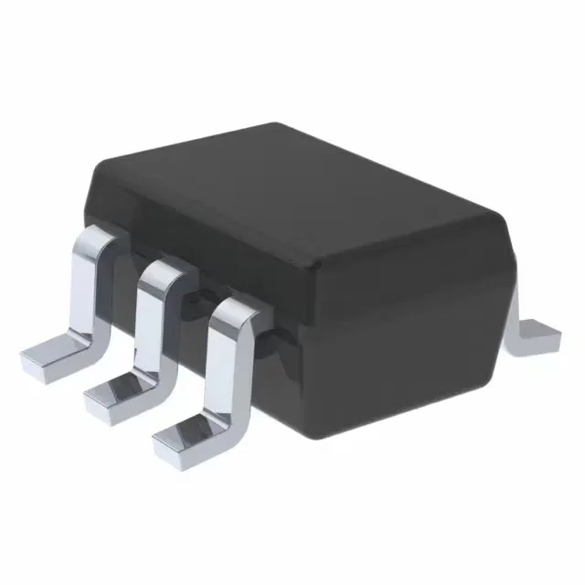
The TPD4E1U06DCKR comes in the SC-70-6 package (also designated as 6-TSSOP, SC-88, SOT-363). If your board is laid out for the SOT-363, the DCKR is the correct variant; if your layout uses the larger SOT-23-6, you need the DBVR. No adapter or workaround — the footprints do not interchange. That covers outdoor telecom cabinets, automotive cabin electronics, and industrial Ethernet switches — environments where the ambient temperature inside the enclosure can exceed 85°C.