100 MHz C28x core — timing margin in the control loop
The 100 MHz clock on the fixed-point C28x core gives you a 10 ns instruction cycle. For a typical 10 kHz current-control loop with a 200-step PI routine, that leaves about 500 ns of headroom after the ADC read and PWM update — tight but workable. If your loop needs more margin or you're running a higher PWM frequency, you'll want to budget the cycle count early in firmware.
That means a dedicated 1.8 V LDO or switcher on the board, not a shared 3.3 V rail. Dropout on the regulator matters here — a 1.8 V output LDO with 200 mV dropout needs at least 2.0 V input. A common gotcha is trying to run this from a 1.8 V rail that sags under load; the POR peripheral will trip and the MCU resets.
That puts it in the cabin or chassis-domain category — fine for infotainment, body control, or a DC-DC converter inside the passenger compartment, but not for an engine ECU or a transmission controller sitting next to a hot exhaust. If the board sees 105°C ambient, this part won't hold.
The part includes a 16-channel, 12-bit ADC, PWM with built-in dead-band, CANbus, I²C, SCI, SPI, and UART/USART. The CAN interface is the main draw for automotive networks — it's a 2.0B controller, so it handles both standard and extended frames.
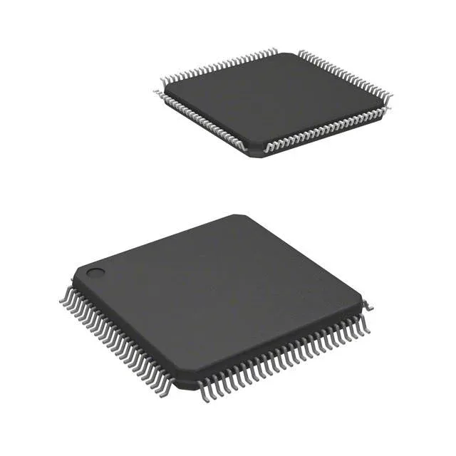
It's a standard surface-mount footprint, reworkable with a hot-air station if you're careful.
That means it's available through the standard TI distribution channel and through independent distributors.