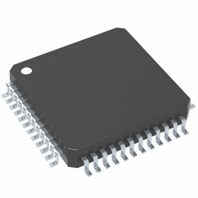
60 MHz C28x core with automotive qualification
On-chip peripherals include a 13-channel 12-bit ADC, PWM channels, a watchdog timer, and brown-out detect/reset.
Supply rail and decoupling — the 1.71 V floor
Any transient dip below 1.71 V triggers the brown-out reset, so the regulator must hold regulation under load steps. A low-dropout linear regulator with a 2.5 V or 3.3 V input and output capacitance of at least 4.7 µF ceramic per the regulator's stability requirements is typical. Place the decoupling capacitors as close to the VDD and VSS pins as the 48-LQFP layout allows, with a 0.1 µF ceramic per supply pin pair and a bulk 4.7 µF on the board.
Memory budget for real-time control firmware
A typical motor-control application — field-oriented control with speed and current loops, plus CAN or SCI communication — fits comfortably in 32 KB to 48 KB of Flash, leaving room for a bootloader and parameter tables. The 6K-word RAM handles a few state arrays and a modest data buffer; if the application requires large look-up tables or extensive data logging, consider moving to the higher-memory F28004x family.
ADC and analog front-end
The 13-channel 12-bit ADC samples at rates sufficient for current sensing in a single motor phase or voltage monitoring on a 12 V automotive bus. The 12-bit resolution gives about 1.2 mV per LSB with a 3.3 V reference, adequate for most shunt-based current measurements. For higher accuracy, an external reference can be used; the internal reference is typical and within tolerance for the majority of automotive sensor feedback loops.
The part is ROHS3 compliant.