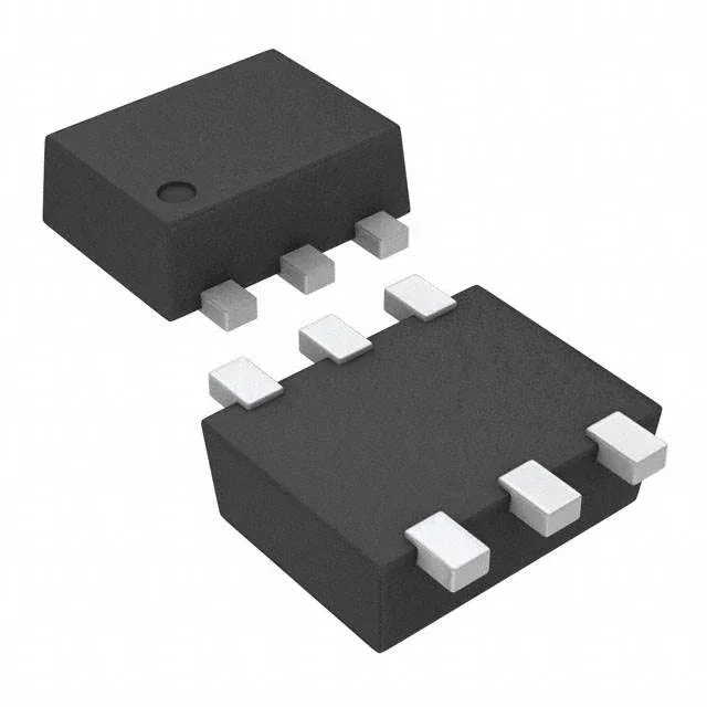
SOT-563 footprint and what it connects to
The TMP20AIDRLR: This is a six-lead surface-mount package with a 0.95 mm pitch — the same footprint used by many small-signal transistors and diodes, so the pad layout is standard and the thermal coupling to the board copper is predictable. The SOT-563 body is roughly 1.6 mm × 1.6 mm with a seated height under 0.6 mm, which places the die close to the board. For a local temperature sensor, this means the reading tracks the PCB copper temperature more closely than the ambient air — the sensor is measuring the board temperature where it is soldered, not the free air. If the application needs ambient air temperature, the sensor should be mounted on a minimal copper island with a thermal relief.
Analog voltage output and what 11.77 mV/°C means for the ADC
The TMP20 outputs an analog voltage proportional to temperature with a resolution of 11.77 mV/°C. This is a linear transfer function — the output voltage decreases as temperature increases, with a slope of -11.77 mV/°C. Over the sensing range of -55°C to +130°C, the output spans roughly 2.2 V down to 0.4 V (at a 2.7 V supply), which maps directly into the input range of a typical microcontroller ADC without external scaling. The 11.77 mV/°C slope means that a 12-bit ADC with a 3.3 V reference gives about 0.08°C per LSB — the ADC resolution is not the limiting factor; the sensor's own noise and accuracy are. The sensor accuracy is ±0.5°C typical over the full range, with a worst-case ±2.5°C across the -55°C to +130°C span. For most system-level temperature monitoring (thermal shutdown, fan control, derating), the ±0.5°C typical figure is sufficient; the ±2.5°C limit matters only if the reading is used for tight calibration or compensation.
Supply voltage range and shutdown mode for power budgeting
This is useful for battery-powered designs where the sensor is read periodically and the supply rail is switched or the sensor's enable pin is toggled. The output voltage at a given temperature shifts with supply voltage, so the ADC reference must track the sensor supply for accurate readings — a ratiometric measurement using the same rail for both sensor and ADC reference eliminates the supply dependency.
Temperature range and deployment context
The TMP20 is specified for local sensing from -55°C to +130°C, with the device itself rated for storage and operation from -55°C to +150°C. The -55°C low end covers cold-soak in aerospace and outdoor telecom equipment; the +130°C high end covers under-hood automotive and industrial motor-drive environments. The test condition range of -50°C to +130°C (-55°C to +130°C) indicates the sensor is characterised across the full span. The -55°C to +150°C absolute maximum operating temperature means the sensor survives brief excursions above the sensing range — for example, during reflow soldering or a nearby hot component — without damage, as long as the junction temperature stays below 150°C. This is a standard industrial temperature grade, not automotive AEC-Q100, but the range itself overlaps with many automotive under-hood requirements.
Lifecycle and compliance documentation
Because the part is active and single-sourced from TI, there is no official second-source or pin-compatible alternative from another manufacturer. For BOM risk management, the TMP20AIDRLR is a sole-source line item — qualify an alternate now if the production volume justifies the effort.