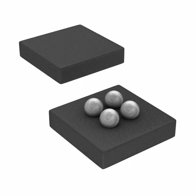
4-DSBGA footprint and board integration
The TMP103DYFFR comes in a 4-DSBGA package measuring 1x1 mm — the smallest footprint for a digital temperature sensor in this accuracy class. The 0.5 mm pitch BGA demands a controlled solder-paste stencil and a 4-layer board for fan-out of the I²C and supply lines. Surface-mount assembly with the 4-UFBGA, DSBGA case means the thermal pad is the bottom of the package itself — no exposed paddle, so the board copper under the sensor acts as the primary heat sink. A thermal via array under the package improves response time to local temperature changes.
±2°C accuracy across the operating band
Accuracy is specified as ±2°C (highest) and ±3°C (lowest) across the -10°C to 100°C test condition, with the sensor rated for local sensing from -40°C to 125°C. The ±2°C figure is the typical tolerance at 25°C; the ±3°C limit covers the full calibrated range and is the figure to use in worst-case error budget analysis for a thermal management loop. The 8-bit resolution gives a step size of 1°C per LSB — adequate for over-temperature protection and fan control where ±1°C granularity is acceptable. For applications needing finer resolution, the TMP103 family's 12-bit sibling (TMP102) provides 0.0625°C per LSB but in a different package.
Supply range and temperature grade
Operating from 1.4V to 3.6V supply, the TMP103DYFFR works on a 1.8V or 3.3V rail without a separate regulator — the I²C/SMBus interface is referenced to the same supply, so no level shifting is needed if the bus voltage matches Vdd. The full operating temperature range of -55°C to 150°C exceeds the standard industrial -40°C to 125°C band, covering cold-start conditions in outdoor telecom and high-temperature engine-bay environments. The -55°C lower limit is the storage and functional minimum, while the -40°C to 125°C sensing range is the calibrated measurement window.
One-Shot and Shutdown Mode for power-cycled sensing
The One-Shot feature lets the firmware trigger a single temperature conversion on demand, then return the device to Shutdown Mode — drawing near-zero quiescent current between reads. This is the right operating mode for battery-powered wireless sensor nodes where the bus is idle 99% of the time. In Shutdown Mode the I²C interface remains active, so the bus master can still address the device without waking it — the conversion starts only when the One-Shot command is sent. The conversion time is typically 15 ms at 25°C, so the firmware must hold off the read until the data register updates.
Active production and compliance
Available in Tape & Reel (TR) or Cut Tape (CT) for prototyping. The 4-DSBGA package is moisture-sensitive — verify the MSL level before opening the reel for hand-assembly rework.