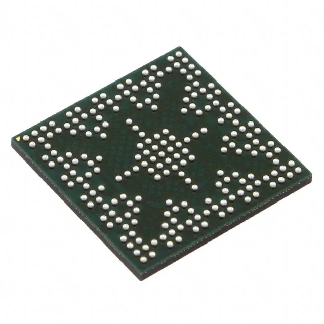
120 MHz Cortex-M4F with integrated Ethernet and CAN — the industrial gateway MCU
The 120 MHz core with single-precision FPU gives enough headroom for sensor fusion math or motor control algorithms alongside the TCP/IP and CAN stacks. Program memory is 1 MB of Flash, backed by 256K x 8 of SRAM and 6K x 8 of EEPROM — the EEPROM is useful for storing calibration constants and configuration parameters without wearing the Flash. The 140 GPIOs in the 212-NFBGA package provide ample interface capacity for parallel displays, external memory buses, and sensor arrays. The connectivity set is what distinguishes this part: Ethernet MAC+PHY, two CAN 2.0 controllers, USB OTG, and multiple UART/USART, I2C, and QSSI (SPI) interfaces. Supply voltage is 2.97 V to 3.63 V, which aligns with standard 3.3 V rail designs.
212-NFBGA (10x10) — layout considerations
Decoupling should follow the layout guidelines in the Tiva C datasheet — typically a 10 µF bulk cap per supply rail plus 100 nF per VDD pair placed within 3 mm of the ball. The 140 I/O are distributed across the BGA ball map; the Ethernet PHY requires specific analog supply pins that should be isolated from the digital supply with a ferrite bead.
Peripherals and data conversion
On-chip data converters include a 24-channel, 12-bit ADC — enough to sample multiple analog inputs from current sensors, thermistors, or potentiometers without external muxing. The peripheral set includes motion-control PWM, a watchdog timer, brown-out detect, POR, DMA, and a motion-control PWM module, covering the typical needs of motor drive and power conversion applications.