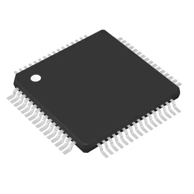
That FPU means you can run sensor-fusion algorithms or PID loops in hardware rather than soft-emulating the math — a real cycle-count saver versus an M3 core at the same clock. Memory budget: 64 KB of Flash for program storage, 24 KB of SRAM for data, and a separate 2 KB EEPROM block for configuration parameters that survive a firmware update. The EEPROM is useful for calibration constants or boot counters without wearing the Flash.
The 43 GPIOs are enough for a modest keypad-and-display interface plus sensor inputs. On-chip connectivity includes USB (device/host/OTG), CAN 2.0, and multiple serial channels (I²C, SPI, SSI, UART, IrDA, Microwire). That CAN interface is the main reason you'd pick this over a simpler Cortex-M0 part — it saves an external CAN transceiver controller and keeps the BOM count down for automotive or industrial bus nodes. A 12-channel, 12-bit ADC handles analog sensor readback; the brown-out detect and POR supervise the supply without an external supervisor IC.
The exposed pad is not present on this package variant — thermal dissipation goes through the leads, so keep the ambient airflow in mind if the core runs sustained DSP loads.
TI lists the TM4C1233D5PMI as Active.