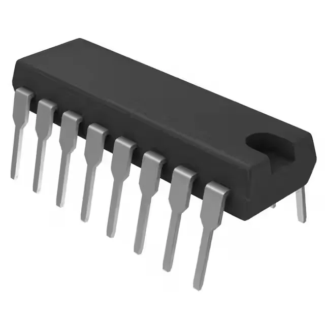
Texas Instruments TL594ING4 — Power Management (PMIC / Gate Driver)

TL594ING4 PWM Controller, 97% Duty Cycle, 16-PDIP

MPNTL594ING4
End of Life

Texas Instruments TL594ING4 PWM controller, 2 outputs, 97% max duty cycle, 1kHz-300kHz switching, 7V-40V supply, 16-PDIP, -40°C to 85°C, Tube.

Independent supplier — new & surplus stockAuthenticity-screened · ESD-safe packingListing updated Jul 2026

Specifications

TL594ING4 specifications
ParameterValue
Output typeTransistor Driver
MountingThrough Hole
Voltage - supply (Vcc (Vdd))7V ~ 40V
Frequency - switching1kHz ~ 300kHz
I/O channels2
Output phases1
Duty cycle97%
Operating temperature-40°C~85°C(TA)
PackageTube
FunctionStep-Up, Step-Down, Step-Up/Step-Down
TopologyBuck, Boost, Flyback, Forward Converter, Full-Bridge, Half-Bridge, Push-Pull
Clock syncNo
Case16-DIP (0.300\", 7.62mm)
Control featuresDead Time Control, Frequency Control
Output configurationPositive
Synchronous rectifierNo

Product details

Its 97% maximum duty cycle means the output can ride within a few percent of the input rail — essential for a boost converter that must hold regulation as the input sags, or for a forward converter that needs to maximise volt-seconds on the transformer primary. The part is in a 16-pin PDIP through-hole package, suited for prototyping, low-volume production, and designs where rework ease matters more than board density.

Switching frequency and supply — sizing the passives

The switching frequency spans 1 kHz to 300 kHz. The supply range of 7 V to 40 V covers standard industrial buses.

Control features and temperature grade

Dead-time control and frequency control are on-chip, letting you set the overlap between the two output phases and synchronise the oscillator to an external clock if needed — though the part does not include a dedicated clock-sync pin, so synchronisation is done by injecting a signal into the RT/CT pin. No synchronous rectifier driver is included, so the output stage uses Schottky or ultrafast diodes on the secondary side.

The 16-PDIP package ships in tube form, which is typical for through-hole ICs in production runs and prototyping alike.

Frequently asked questions

What is the maximum duty cycle of TL594ING4?

The maximum duty cycle is 97%. This allows the output to regulate very close to the input rail, which is critical in boost and forward-converter designs that need to maintain output voltage as the input drops.

Does TL594ING4 support external synchronization?

The TL594ING4 does not have a dedicated clock-sync pin. External synchronization can be achieved by injecting a synchronising signal into the RT/CT timing pin, but the part does not include a built-in clock-sync function.

Is TL594ING4 pin compatible with TL494?

The TL594 is a functional upgrade of the TL494 with improved dead-time control and a higher maximum duty cycle. The pinout is the same 16-pin PDIP layout, so TL594ING4 is a drop-in replacement for TL494 in most designs, provided the supply voltage and frequency range match the application.