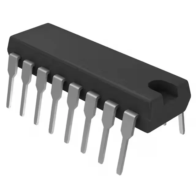
The Texas Instruments TL594IN is a fixed-frequency PWM controller built for a wide range of isolated and non-isolated topologies — buck, boost, flyback, forward converter, half-bridge, full-bridge, and push-pull. It drives a pair of transistor outputs with a single output phase, configurable for positive output polarity.
Switching frequency and duty cycle — the design envelope
The oscillator runs from 1 kHz to 300 kHz, set by an external RT and CT. That range covers most line-frequency and medium-frequency transformer designs for industrial power supplies and motor-drive housekeeping rails. The 97% maximum duty cycle is a practical ceiling for flyback converters that need long on-times to charge the primary inductance at low input voltage — the off-time reset voltage on the primary switch is the constraint, not the controller.
Supply range and control features
Vcc range is 7 V to 40 V, which covers 12 V and 24 V industrial buses, 36 V battery stacks, and the auxiliary winding of a 48 V telecom supply without an external regulator. The controller includes dead-time control and frequency control pins — dead-time adjustment lets you tailor the off-time margin for transformer core reset in half-bridge and push-pull stages. There is no clock sync input, so multiple TL594INs free-run; for synchronised multi-phase rails you would look at a PLL-based controller.
16-pin PDIP, 0.300-inch body width. The through-hole leads are 0.025-inch square, plated for solderability. The plastic body is standard epoxy; no moisture-sensitive level (MSL) concern for hand-soldering or wave-solder. If you need to pull one off a board, the leads are robust enough that you can desolder with a solder sucker or desoldering braid without lifting a pad — a QFN this is not.