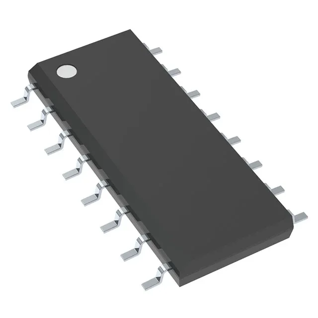
PWM controller for multi-topology power supplies
The Texas Instruments TL594CDRG4 is a fixed-frequency PWM controller that drives two transistor outputs for step-up, step-down, or step-up/step-down converters. It supports buck, boost, flyback, forward converter, half-bridge, full-bridge, and push-pull topologies — one part number covers a wide range of isolated and non-isolated designs.
Switching frequency and duty cycle — design budget
The oscillator runs from 1kHz to 300kHz, set by an external RT and CT. The 97% maximum duty cycle leaves only 3% dead time per cycle — important for forward converters where the reset winding must saturate before the next on-time, and for boost stages that need a long on-time at low input voltage.
Supply range and control features
The Vcc range of 7V to 40V lets the controller run directly from a 12V, 24V, or 48V industrial bus without a separate bias supply. Dead-time control and frequency control pins give the designer adjustment over the output waveform — the dead-time pin can be used to implement soft-start or to limit the maximum duty cycle below 97%.
The narrow-body SOIC limits power dissipation compared to a wide-body package — the total junction-to-ambient thermal resistance is higher, so the designer must account for the controller's own power draw plus the gate-drive current when sizing the thermal footprint.
The Tape & Reel (TR) packaging is the standard shipping form for the 16-SOIC body.