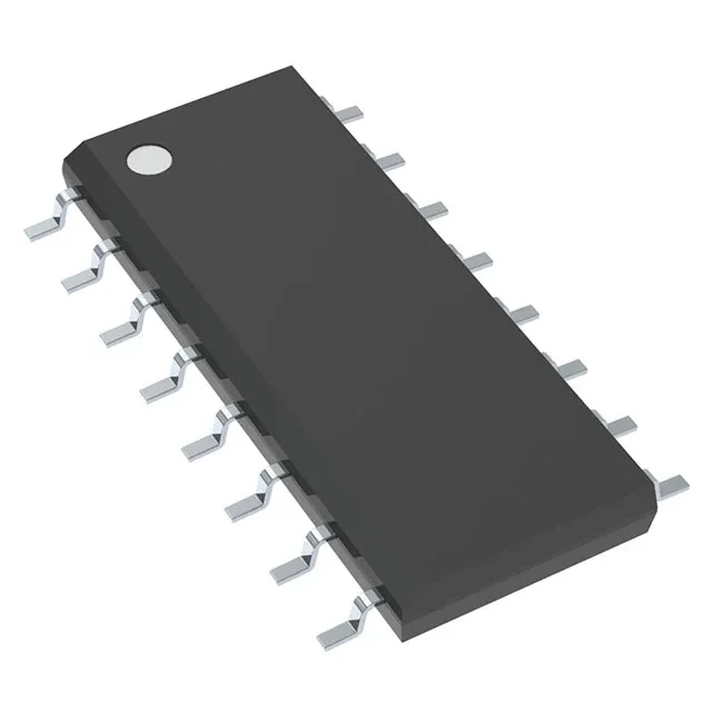
TL594CDR

Texas Instruments

Texas Instruments TL594CDR, PWM Controller IC, Step-Up/Step-Down/Step-Up/Step-Down, 1 kHz ~ 300 kHz, 97% Duty Cycle, 2 Outputs, Transistor Driver, 7 V ~ 40 V Supply, 16-SOIC Surface Mount, 0 °C ~ 70 °C.

Texas Instruments TL594CDR
Download datasheet (PDF)
[IN STOCK] In Stock: 180 pcs
$0.87/ pc

Volume pricing

Buy Now

MOQ 1 · Tape & Reel (TR); Cut Tape (CT) · RoHS · EIA-481 · DAP/DDP · T/T

Technical specifications

TL594CDR specifications
Parameter / AttributeSpecification / Value
Output typeTransistor Driver
MountingSurface Mount
Voltage - supply (Vcc (Vdd))7V ~ 40V
Frequency - switching1kHz ~ 300kHz
I/O channels2
Output phases1
Duty cycle97%
Operating temperature0°C~70°C(TA)
PackageTape & Reel (TR); Cut Tape (CT)
FunctionStep-Up, Step-Down, Step-Up/Step-Down
TopologyBuck, Boost, Flyback, Forward Converter, Full-Bridge, Half-Bridge, Push-Pull
Clock syncNo
Case16-SOIC (0.154\", 3.90mm Width)
Control featuresDead Time Control, Frequency Control
Output configurationPositive
Synchronous rectifierNo

Technical details

What this PWM controller does on your board

The TL594CDR: Switching frequency spans 1 kHz to 300 kHz. Maximum duty cycle is 97 %. Supply range is 7 V to 40 V. Two totem-pole transistor-driver outputs handle external MOSFETs or bipolar switches directly.

Dead time control and frequency setting — what to watch

Dead time is adjustable via a pin, which means you can program overlap protection for half-bridge and push-pull stages without adding external logic. Frequency is set by an external RT and CT — no internal oscillator trim, so keep the RC tolerance in your BOM budget if tight regulation matters. The controller lacks clock sync, so if you are paralleling multiple converters, expect beat frequencies unless you slave them to a master timing signal externally.

It belongs in indoor power supplies, telecom rectifiers, office equipment, and appliance PSUs.

TL594CDR
[ALLOC] verified
Quote