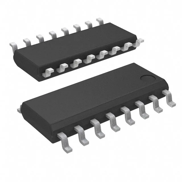
PWM controller with 97% duty cycle ceiling
The TL594CDE4 is a fixed-frequency PWM controller from Texas Instruments that handles step-up, step-down, and step-up/step-down topologies including buck, boost, flyback, forward converter, full-bridge, half-bridge, and push-pull. Its 1 kHz to 300 kHz switching range lets you tune the power stage for magnetics size versus switching loss — 50 kHz for a through-hole transformer in a legacy supply, 200 kHz for a planar magnetics board in a compact converter.
Supply rail and drive capability
Operates from a 7 V to 40 V supply, which means it can run off a regulated 12 V rail or a raw 24 V industrial bus without a pre-regulator. The two transistor-driver outputs deliver complementary or single-ended drive with a 97% maximum duty cycle — useful for push-pull and forward converters where you need to squeeze the last few percent of output voltage from a given transformer turns ratio.
Control features for loop tuning
Includes dead-time control and frequency control pins — you can program the dead time externally to prevent cross-conduction in half-bridge or push-pull stages, and synchronise the oscillator frequency with an external resistor and capacitor. No clock sync input, so for multi-phase systems you'd need a master oscillator feeding the RT/CT pin.
That's commercial temperature range — fine for bench supplies, office equipment, and indoor industrial controls. Not rated for -40 °C cold-crank or under-hood automotive, so if the board lives in a heated cabinet it's fine; if it's on a forklift in a freezer warehouse, budget for a wider-temp variant.
No official second-source cross-reference is carried in the listing, but the TL594 family has been second-sourced historically — verify pin-compatibility against your BOM's specific date-code requirements.