Shunt reference with a 2.495 V floor — what the adjustable range means
Its output voltage is set by two external resistors from the 2.495 V minimum reference up to 36 V maximum, making it a drop-in precision voltage setpoint for feedback loops in switch-mode power supplies, linear regulators, and isolated DC-DC converters.
100 mA cathode current — the load budget for your feedback divider
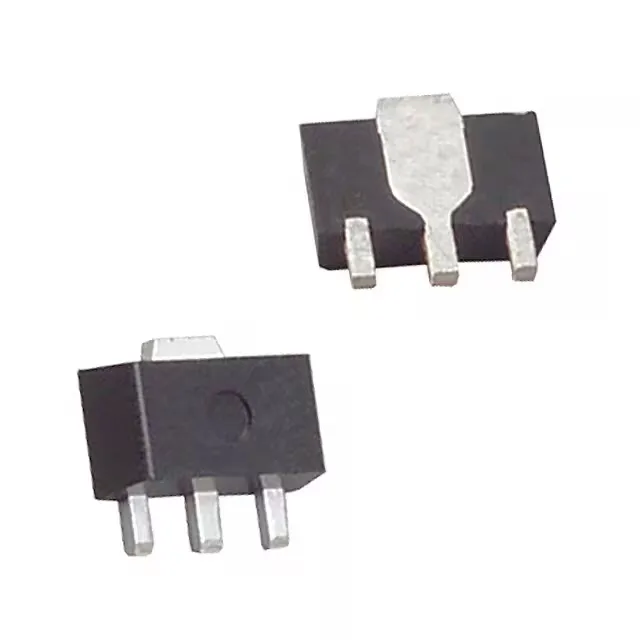
The shunt can sink up to 100 mA of continuous cathode current. In a typical feedback application, the cathode current is the sum of the bias current through the resistor divider and any external load. The 700 µA minimum cathode current (Ika(min)) ensures the device stays in regulation; below that the output voltage drifts. Design the divider so the total cathode current stays between 700 µA and 100 mA across all load and temperature conditions. The SOT-89-3 package (TO-243AA) has a large collector tab that conducts heat to the PCB copper. For continuous operation near the 100 mA ceiling, ensure the tab is soldered to a sufficient copper area — the datasheet's thermal impedance curves assume a minimum pad size. Running 100 mA at 125°C ambient without adequate copper can push the junction temperature above the 150°C absolute maximum.
Active lifecycle — no last-time-buy clock on this BOM line
Dual-sourcing with the TL431 in SOT-23 or TO-92 is straightforward if the board layout accommodates the different footprint.