Adjustable shunt reference with an AEC-Q100 pedigree
It delivers a ±1% tolerance reference voltage with an adjustable output from 2.495 V to 36 V, driven by a 15 mA output current capability and a 600 µA minimum cathode current for bias.
±1% tolerance — the accuracy floor for the feedback loop
A ±1% tolerance on the 2.495 V internal reference translates to a maximum 24.95 mV deviation at the reference pin. For a 12 V output rail using a divider ratio of 4.8:1, this tolerance contributes roughly ±120 mV to the output regulation band — a predictable margin the designer budgets into the load-regulation spec. The adjustable output topology (set by two external resistors) means the same ±1% reference tolerance propagates through the divider ratio; the wider the ratio, the larger the absolute output spread. For tight-rail requirements, use the TL431LIAQDBZRQ1 with a divider that keeps the output deviation within the load's tolerance window.
SOT-23-3 package: footprint and thermal routing
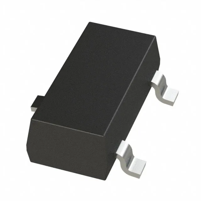
The SOT-23-3 (TO-236-3, SC-59) surface-mount package occupies roughly 3 mm × 1.4 mm of board area. The cathode tab is the primary heat path — a short, wide copper trace to the tab pad keeps the junction temperature rise under 20°C at 15 mA output in still air. The 600 µA minimum cathode current ensures the device stays in regulation even at no load; the designer must ensure the bias resistor from cathode to supply delivers at least this current across the full input voltage range.
The base product number is TL431, a long-running industry-standard family.