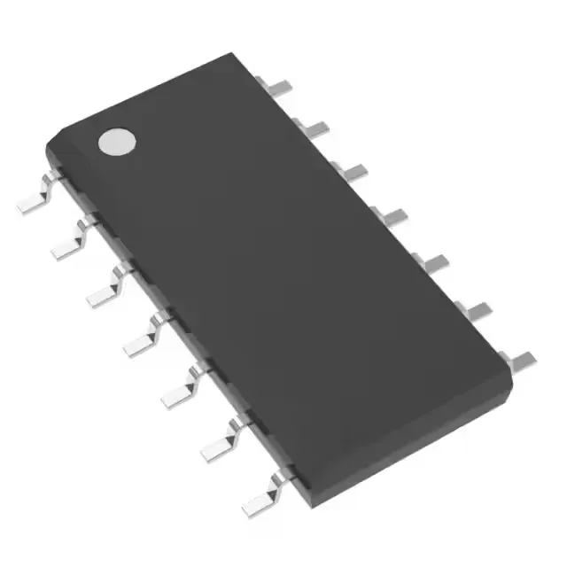
500 kHz current-mode PWM controller for boost, flyback, and forward converters
The ON Semiconductor TL2842BD is a current-mode PWM controller designed for step-up and step-up/step-down topologies including boost, flyback, and forward converters. It delivers a single transistor-driver output with a maximum duty cycle of 96%, allowing wide conversion ratios without an extra winding or charge pump. The switching frequency runs up to 500 kHz, which lets the designer shrink the transformer and output filter magnetics compared to lower-frequency controllers — useful for space-constrained industrial power supplies, bias rails in motor drives, and isolated telecom converters.
Supply voltage and control features
The controller operates from a 10 V to 30 V Vcc supply, so it needs a bias rail above 10 V — not a 5 V-only bus. A frequency-control pin is provided for external timing adjustment, but the part does not include clock synchronization or synchronous rectification, so the designer handles multi-phase alignment externally and uses a freewheeling diode on the output. The output configuration is positive, and the output type is a transistor driver, meaning the gate-drive signal is intended to drive an external power switch (typically a MOSFET) through a series resistor.
No official second-source alternate is listed in the manufacturer's cross-reference, but the UCC2806DWTR is a functional peer with a 50% duty-cycle limit and dual outputs, suited for designs that need synchronous rectification or two-phase operation.