What the 5 ns propagation delay means for your timing budget
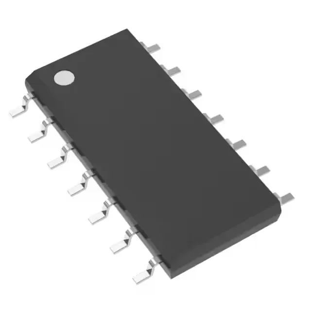
The SN74S32D: This delay sets the upper bound on the data rate through the gate — in a 5 V logic system clocked at 50 MHz, the gate adds one full clock period of latency per stage, so cascading multiple gates in a critical path eats into setup margin. The output drive is rated 1 mA source and 20 mA sink at the logic thresholds. The 20 mA sink capability is enough to drive a standard TTL input or a small LED directly, but the 1 mA source limit means the gate cannot drive a heavy capacitive load without slowing the rise time — the 5 ns spec assumes 50 pF, so a longer trace or multiple fan-out adds delay beyond the datasheet maximum.
Supply voltage and temperature envelope
The input thresholds are 0.8 V low and 2.0 V high, which are compatible with standard 5 V TTL and CMOS logic families. The commercial temperature range (0°C to 70°C) limits deployment to indoor, controlled environments — not suitable for automotive or industrial extended-temp applications without qualification. Quiescent current is 32 mA maximum, which is typical for the 74S Schottky family — the Schottky clamp transistors reduce propagation delay at the cost of higher static power. In a battery-powered or thermally constrained design, this part draws more standby current than a 74LS or 74HC equivalent, so the power budget must account for the 160 mW dissipation at 5 V.
The tube packaging means the parts are shipped in anti-static tubes, not tape-and-reel, so pick-and-place feeders may require a tube feeder or manual loading for volume assembly.