What this part does on the board
It sits between two voltage domains — one port tracks VCCA, the other VCCB — and bidirectionally translates logic levels across the 1.65V to 5.5V range on each side. The 3-state outputs let you share a bus without contention, and the 32mA symmetric drive handles typical automotive loads like ECU-to-sensor interfaces or gateway-to-module links.
Supply range and voltage-domain bridging
Each supply pin accepts 1.65V to 5.5V independently, so you can translate between a 1.8V MCU and a 5V peripheral, or between 3.3V and 5V CAN transceivers, without an external level shifter. The device powers up with outputs in high-impedance state, preventing bus glitches during power sequencing.
Output drive and bus architecture
Each of the eight channels can source or sink 32mA, enough to drive a short twisted-pair stub or an LED indicator without a buffer. The 3-state control (active-low output enable per element) lets you isolate the bus during diagnostics or when the ECU enters sleep mode.
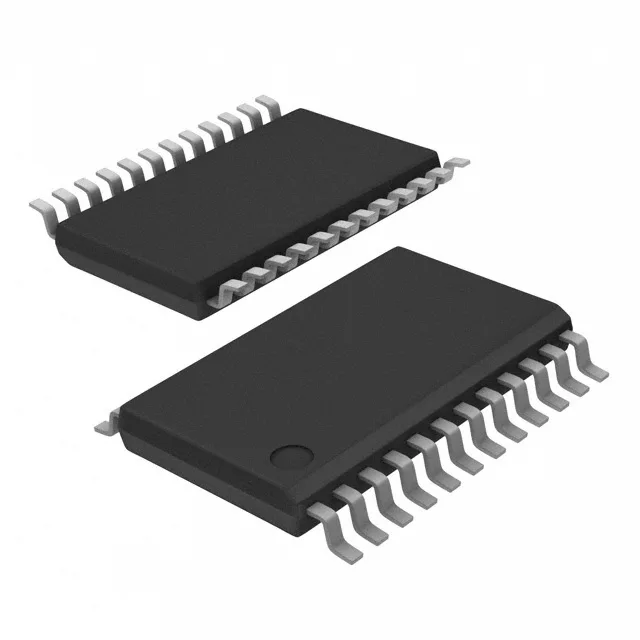
Housed in a 24-TSSOP (4.40mm body width), the QPWRQ1 suffix indicates the automotive-qualified, tape-and-reel variant. The 0.65mm pitch is standard for this package class; the footprint matches the generic 24-TSSOP land pattern in most CAD libraries.