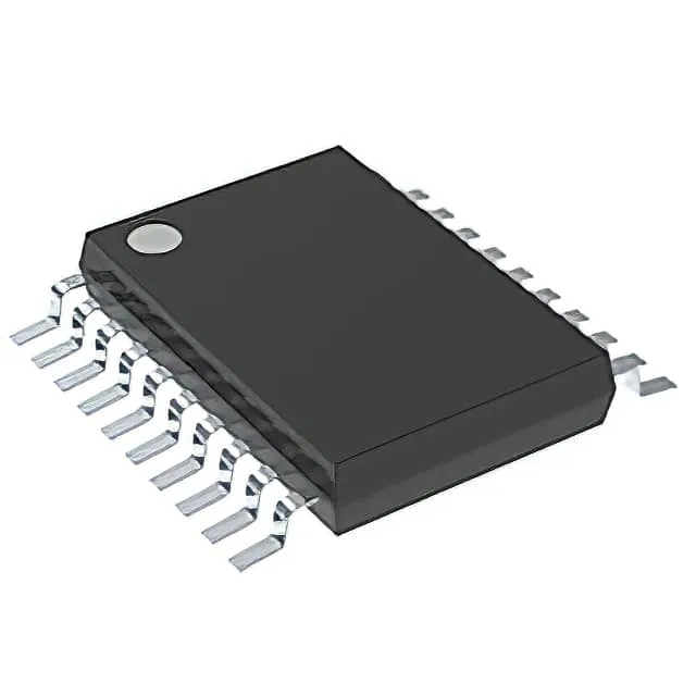
The SN74HCT645PW: It integrates one element with eight bits per element, each channel capable of sinking or sourcing 6 mA. The 3-state outputs let you isolate the bus when the device is disabled, which is standard for shared data lines in microcontroller or DSP systems.
6 mA output drive — the fan-out constraint on a loaded bus
The 6 mA source and sink rating is typical for HCT logic and matches the original 74HCT standard. If you are used to the 32 mA drive of the 74ABT2245DW or the 74LVTH16245ADGVR, this part will not drive a heavily loaded backplane or a long unterminated trace without buffering. For a point-to-point link between two CMOS devices or a short board-level bus, 6 mA is adequate. The trade-off is lower dynamic power and a simpler supply — no need for a separate 3.3 V rail — which keeps the BOM lean for a 5 V-only system.
That means no last-time-buy window looming, no end-of-life notice to track. For a production BOM, this part is a low-risk line item — you can qualify it for new designs and expect consistent supply through franchised distribution and independent channels alike.
20-TSSOP footprint — what the layout engineer needs to know
It is not a QFP or BGA, so inspection and rework are straightforward with a hot-air station and microscope. The 0.173" (4.40 mm) width means it fits on a standard 0.1" grid prototyping board only if you use a breakout adapter. For production, the PCB footprint follows the JEDEC MO-153 standard for TSSOP-20. Keep the decoupling capacitor within 5 mm of the supply pin to maintain signal integrity on the 5 V rail.