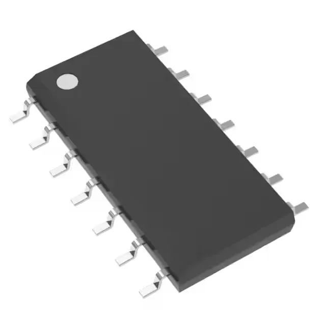
Active production — what it means for the BOM
The SN74HCT04D: For a BOM line that uses this hex inverter, there is no urgency to qualify a second source or stockpile ahead of a phase-out. ROHS3 compliant, so it passes the current EU and UKCA restricted-substance requirements without an exemption expiry to track.
Hex inverter — TTL-compatible thresholds in a 5V logic rail
Six independent inverter gates, each with a single input, in a 14-SOIC package. Input logic thresholds are set at 0.8 V low and 2 V high, matching TTL levels. This means the part directly interfaces with 5 V TTL outputs without external level translation, and the 2 µA max quiescent current keeps the idle draw negligible in battery-backed or always-on domains. Output drive is symmetric at 4 mA source and 4 mA sink — enough to drive a single standard TTL load or a low-power LED through a series resistor, but not intended for bus or high-fan-out applications without buffering.
Timing margin — 18 ns propagation delay at 5.5 V
Maximum propagation delay is 18 ns at 5.5 V supply with a 50 pF load. This sets the timing budget for a single gate in a logic chain — at a 10 MHz clock, the 100 ns period leaves about 82 ns of margin after the gate delay, so a chain of four gates still clears the setup time of a downstream flip-flop. The delay is specified at the worst-case supply (5.5 V) and load (50 pF), so actual delay at 5.0 V and lighter loads will be shorter — but the 18 ns figure is what you use for timing closure.
Temperature grade and board integration
This covers most factory-floor, outdoor telecom cabinet, and automotive cabin applications — but not under-hood or engine-bay where 125°C is required. Surface-mount 14-SOIC (0.154" body width, 3.90 mm) — the standard small-outline footprint that fits a 1.27 mm pitch layout. The tube packaging means it ships in antistatic tubes, not tape-and-reel, so it is suited for hand-assembly or low-volume pick-and-place runs.