60 MHz clock and 30 ns propagation delay
The SN74HC74QDRG4Q1: The 60 MHz maximum clock frequency sets the toggle rate ceiling — the flip-flop can capture data edges at 60 ns intervals. The 30 ns propagation delay at 6V and 50 pF load defines the timing budget from clock edge to output valid; at lower supply voltages the delay increases per the HC family curve, so the actual system clock rate may need to be derated when operating near 2V. The 4 µA quiescent current keeps the power budget low in battery-backed or always-on sections.
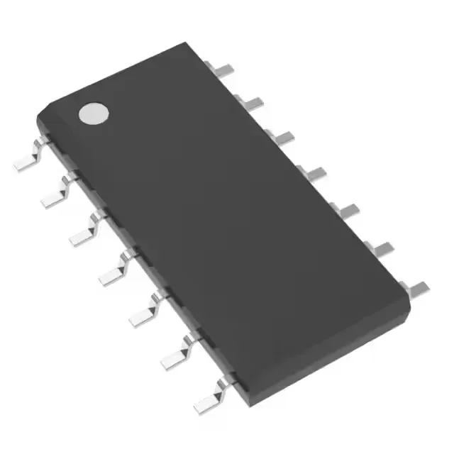
14-SOIC package and board fit
Input capacitance is 3 pF typical, which keeps the clock line loading low enough for daisy-chaining multiple flip-flops on the same trace without a dedicated buffer.
Set and reset with complementary outputs
The D-type flip-flop includes independent Set (Preset) and Reset inputs, allowing the output to be forced high or low regardless of the clock state — useful for initialization sequences or asynchronous override in safety-critical logic. The complementary outputs (Q and Q-bar) provide both true and inverted signals from a single element, saving an external inverter. Positive edge triggering means data is captured on the rising clock edge — standard for most synchronous logic designs. The dual-element configuration (two flip-flops per package) matches the footprint of the industry-standard 74HC74 function.
Sourcing and compliance
ROHS3 compliant, the part meets the European Restriction of Hazardous Substances directive for lead-free soldering processes. The active lifecycle status means no last-time-buy windows or supply constraints from the manufacturer.