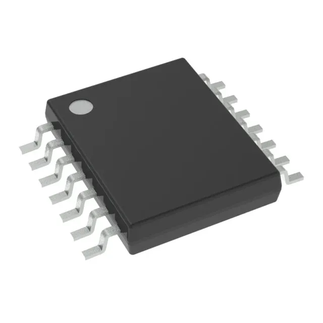
Texas Instruments SN74HC08IPWRG4Q1 — Analog & Data Acquisition

SN74HC08IPWRG4Q1 Texas Instruments AND Gate, 4-ch, 2-input

MPNSN74HC08IPWRG4Q1
End of Life

Texas Instruments Automotive, AEC-Q100 74HC series, SN74HC08IPWRG4Q1 AND Gate, 4 circuits, 2 inputs, 14-TSSOP package, 2V to 6V supply, -40°C to 85°C.

$0.69Ref. price · indicative, final on quote
Packaging14-TSSOP (0.173", 4.40mm Width)
StockContact for availability
Lead timeIn Stock wk
MOQ1 pcs
  • 100% new & originalTraceable channels only — no refurbs, no pulls, no remarked parts.
  • Date & lot codes on quoteStated per line before you commit; label photos on request.
  • MSL-compliant ESD packingMoisture-sealed bags with indicator cards; reels photo-verified.
  • PayPal buyer protectionPay by T/T, PayPal or Payoneer — card payments covered end to end.

Specifications

SN74HC08IPWRG4Q1 Technical Specifications
ParameterValue
SeriesAutomotive, AEC-Q100, 74HC
Logic typeAND Gate
Mounting typeSurface Mount
Voltage2V ~ 6V
Current - quiescent2 µA
Current - output high, low5.2mA, 5.2mA
Number of inputs2
Operating temperature-40°C ~ 85°C
PackageTape & Reel (TR); Cut Tape (CT)
Case14-TSSOP (0.173\", 4.40mm Width)
Number of circuits4
Input logic level - low0.5V ~ 1.8V
Input logic level - high1.5V ~ 4.2V
Max propagation delay @ v, max CL17ns @ 6V, 50pF

Product details

The SN74HC08IPWRG4Q1 is a Texas Instruments quad 2-input AND gate from the Automotive, AEC-Q100 qualified 74HC logic family. It integrates four independent AND gates, each with two inputs, in a single 14-TSSOP package. Operating from a 2V to 6V supply, this device is designed for automotive and industrial temperature environments spanning -40°C to 85°C.

What the propagation delay and output drive mean for your timing budget

Maximum propagation delay is 17 ns at 6V with a 50 pF load — this sets the upper bound on the data path latency through one gate stage. For a 5V rail the delay is typically shorter, but the 17 ns ceiling is what you budget for worst-case timing closure across temperature and supply tolerance. Driving a heavily loaded bus or long trace may require a buffer. Quiescent current is a maximum of 2 µA across the full supply range — the gate draws negligible supply current when the outputs are static, making it suitable for battery-backed or always-on modules in the vehicle.

Input logic thresholds and supply flexibility

The input logic-low threshold spans 0.5V to 1.8V, and the high threshold spans 1.5V to 4.2V, both referenced to the supply. This means the gate interprets a 1.8V signal as a logic low at a 2V supply, but the same 1.8V signal is a logic high at a 5V supply — the threshold scales with VCC per the 74HC family characteristic.

Frequently asked questions

What is the closest pin-compatible alternative to SN74HC08IPWRG4Q1?

The 74HC08 in the same 14-TSSOP package from other manufacturers may also be footprint-compatible, but verify the input threshold and output drive ratings against your BOM requirements.

What is the typical power consumption of the SN74HC08IPWRG4Q1?

Dynamic power consumption depends on the switching frequency and load capacitance — for a 50 pF load at 1 MHz, each gate draws roughly ICC = Cpd × VCC × f + ICC(Q). The 74HC family's power dissipation capacitance (Cpd) is typically 20-30 pF per gate.

Who supplies SN74HC08IPWRG4Q1 and how is it quoted for volume purchases?

The SN74HC08IPWRG4Q1 is sourced through independent and authorized distribution channels. For volume pricing and lead time, submit an RFQ specifying your annual usage quantity and preferred delivery schedule.