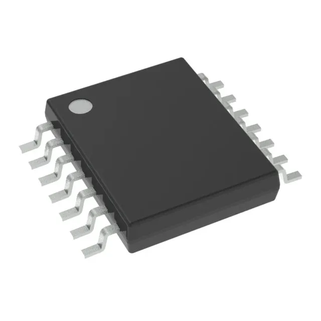
Open-drain NAND in a 14-TSSOP — what the specs mean for the board
The SN74HC03PW packs four independent 2-input NAND gates with open-drain outputs into a 14-TSSOP package — a 4.40 mm wide surface-mount footprint that fits tight layouts where a pull-up resistor on each output lets you wire-OR multiple gates onto a shared bus without contention. Supply voltage spans 2 V to 6 V, so the same part works in a 3.3 V microcontroller interface or a 5 V industrial logic rail — no level translator needed as long as the pull-up voltage matches the receiving side. Each output sinks 5.2 mA when low; the high side is open, meaning the output transistor is off — the pull-up resistor does the work. That 5.2 mA sink is enough to drive an LED directly or pull a bus line low without an external buffer transistor.
Timing and temperature — where the 23 ns delay matters
Maximum propagation delay is 23 ns at 6 V with a 50 pF load — that is the worst-case from input crossing the threshold to output going low. For a 10 MHz clock, that delay consumes about 23 % of a 100 ns period, so the part is comfortable in sub-10 MHz buses but not in a 50 MHz memory-mapped interface. Quiescent current max is 2 µA — negligible in battery-powered designs; the open-drain outputs draw no supply current when the gate is idle.
RoHS3 compliant, with no exemptions that would restrict EU or UKCA market access.