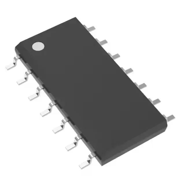
Dual 4-input AND gate in the 74F family
The SN74F21D is a dual 4-input AND gate from Texas Instruments' 74F series, a high-speed logic family that sits between the original 74LS and the later 74AC/ACT in the TTL logic evolution. It packages two independent AND gates, each with four inputs, in a single 14-SOIC package. The 5.1 ns maximum propagation delay at 5 V with a 50 pF load means this gate toggles at roughly 100 MHz in a typical board-level interconnect — fast enough for glue logic in 8- and 16-bit microprocessor systems, but not for the multi-GHz clock trees of modern SoCs.
Output drive and logic thresholds
The output can source 1 mA and sink 20 mA — the asymmetric drive is typical of TTL totem-pole outputs. The sink capability is enough to drive a standard TTL input fan-out of 10, or a low-power LED indicator through a series resistor. The high-side sourcing limit is the constraint: driving a 50 Ω transmission line requires an external pull-up or a buffer. Input logic thresholds are 0.8 V for low and 2 V for high, matching the standard TTL interface. A 3.3 V CMOS output driving this gate's input needs a pull-up to 5 V to guarantee the 2 V high threshold is met — the 74F input does not recognise 3.3 V as a valid high without level translation. Quiescent supply current is 4.3 mA maximum — negligible in a mixed-signal board but worth noting if the gate is on a power-rail that also feeds an analog front-end.
Package and board-fit
A standard SOIC-14 land pattern works; the 0.154" width is the narrow-body variant, so the 0.300" wide SOIC-14 footprint does not fit. The supplier device package is also 14-SOIC, confirming the same mechanical outline. For reflow assembly, the tube-to-reel transfer is a standard service; confirm the tube count at RFQ if you need a specific reel quantity.
This is a mature, stable part that will remain available through standard distribution for the foreseeable future.