Schmitt-trigger input cleans up noisy signals
The SN74AHC1G14DBVT is a single inverter with Schmitt-trigger inputs, meaning it provides hysteresis between the low-to-high and high-to-low switching thresholds. This makes it the right choice for debouncing a switch edge, squaring up a slow-rising sensor output, or cleaning a clock line that picks up coupled noise — a plain inverter would oscillate or double-trigger on the same waveform. The hysteresis band is defined by the input logic levels: low threshold is 0.9 V to 1.65 V, high threshold is 2.2 V to 3.85 V (both at 5 V supply). A signal that crosses the band cleanly sees a single output transition; one that hangs in the middle gets rejected.
Supply voltage and temperature grade cover most boards
The output swings rail-to-rail, so the downstream logic sees a full-swing signal. An outdoor IoT node that sees 85°C in the sun or an engine-bay sensor interface that hits 105°C stays within the operating envelope. Quiescent current is 1 µA max. In a battery-powered design that sleeps most of the time, the inverter's own draw is negligible — the system shutdown current stays below the microamp range.
SOT-23-5 footprint and output drive
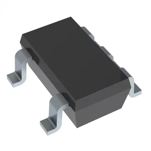
Housed in the SOT-23-5 package (SC-74A, SOT-753), the part takes up about 3 mm × 3 mm on the board — no room wasted for a single-gate function. Output drive is 8 mA sink and 8 mA source at 5 V. That lights a standard LED directly or drives the input of a CMOS gate without a buffer. Propagation delay is 10.6 ns max at 5 V into a 50 pF load — fast enough for most GPIO toggling and sensor readout rates below 50 MHz.
Active production, single-sourced
ROHS3 compliant per the manufacturer's declaration. No known PCN affecting the SOT-23-5 package variant as of the latest revision.