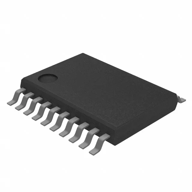
PCF8574PWR

Texas Instruments

Texas Instruments PCF8574PWR, 8-bit I²C I/O expander, 100 kHz clock, push-pull outputs, 1 mA source / 25 mA sink, 2.5 V to 6 V supply, -40°C to 85°C, 20-TSSOP package.

Texas Instruments PCF8574PWR
Download datasheet (PDF)
[IN STOCK] In Stock: 185 pcs
$1.59/ pc

Volume pricing

Buy Now

MOQ 1 · Tape & Reel (TR); Cut Tape (CT) · RoHS · EIA-481 · DAP/DDP · T/T

Technical specifications

PCF8574PWR specifications
Parameter / AttributeSpecification / Value
Output typePush-Pull
MountingSurface Mount
Supply voltage2.5V ~ 6V
Current - output source (Sink)1mA, 25mA
Clock frequency100 kHz
InterfaceI²C
Operating temperature-40°C~85°C
PackageTape & Reel (TR); Cut Tape (CT)
FeaturesPOR
Number of i (O)8
Case20-TSSOP (0.173\", 4.40mm Width)
Interrupt outputYes
100% Footprint Match · Solder-Ready (No PCB Redesign Needed)

Need Stock or a Drop-in Second-Source for PCF8574PWR?

Package: DIP-16 / SOIC-16 (SSOP-20 variant) · Pin-compatible replacements with immediate Shenzhen spot stock

Footprint Match 99%
Supply Chain & Allocation Reality:

The PCF8574 is the 8-bit I2C port expander of button matrices, relay cards, LCD backpacks and a thousand hobby and industrial boards: eight quasi-bidirectional pins, an interrupt output, and three address pins - with one family quirk that fills every forum: the A suffix is the SAME chip at a DIFFERENT I2C address. The plain part answers at 0x20-0x27, the A part at 0x38-0x3F, pin for pin and function for function per both NXP and TI - and the cheap module trade ships whichever die was cheaper that month, label notwithstanding. The other half of this page is behavioral: a quasi-bidirectional port is not a normal GPIO, and its write-1-to-read law explains most "the input does not work" posts in existence.

Verified Pin-Compatible Replacements (3 verified alternatives)

PCF8574A NXP / TI DIP-16 / SOIC-16
Pin-to-Pin (Minor Clock/Init Tuning)
Availability & Target Pricing:

The A Suffix: Same Chip, Different Address

Shenzhen Spot Stock (24-48h Dispatch)

Electrical & Core Specs:

Electrical and functional identical - documented pin-for-pin and function-for-function by both vendors - with one firmware-visible fact: the fixed part of the I2C address is 0111 instead of 0100, moving the base from 0x20 to 0x38 (A0-A2 still pick one of eight).

Same 2.5-6V class and same bus behavior.

Compatibility & Drop-In Notes: The substitution rule is one constant: fitting the A part where the plain part lived works at the pin level and changes the firmware address (or the reverse). In closed-firmware equipment the suffix IS the compatibility - check the BOM, not the socket.
Package & Solder Footprint: Same 16-pin body; the SSOP-20 variant has a different layout - match the package.
Shenzhen Warehouse Stock & MOQ: Both dies stocked; state the suffix explicitly on the order.
MCP23017 Microchip DIP-28 / SOIC-28
Functional Equivalent
Availability & Target Pricing:

The Register-Mapped Modern Alternative

Shenzhen Spot Stock (24-48h Dispatch)

Electrical & Core Specs:

The other school of I2C expansion: 16 bits with true configuration registers - a direction register per port, programmable pull-ups, interrupt-on-change with captured state - where the PCF family has one quasi-bidirectional port and behavioral rules.

Same I2C culture with its own address range and pinout.

Compatibility & Drop-In Notes: Not a substitution - a different architecture for the same requirement. Where a board is being redesigned anyway, the register-mapped part is the modern default; where the PCF board is being repaired, stay in the PCF family.
Package & Solder Footprint: 28-pin body against the 16-pin PCF - different build entirely.
Shenzhen Warehouse Stock & MOQ: Stocked; the redesign recommendation with the reasons stated.
PCF8574 modules (market grade) Various (open market) Module boards
Functional Equivalent
Availability & Target Pricing:

The Module Lottery - Scan Before Trust

Shenzhen Spot Stock (24-48h Dispatch)

Electrical & Core Specs:

The breakout boards sold as "PCF8574": frequently carrying the A-suffix die, with the address set by jumpers or traces whose defaults vary by batch - the same part and the same law, under a label that may not match the die.

Same I2C practice: bus pull-ups present on most modules, verify on all.

Compatibility & Drop-In Notes: Two lines save an evening: scan, then code the address you SAW. The module label, the marketplace listing and the schematic legend are all secondary evidence.
Package & Solder Footprint: Module pin order varies between vendors - check the header labels against the module drawing.
Shenzhen Warehouse Stock & MOQ: Photographed lots with the responding address noted per batch where we can.
Buyer & Quality Checklist for Sourcing Alternatives
  • The suffix is the address and only the address: PCF8574 answers at 0x20-0x27, PCF8574A at 0x38-0x3F, both pin-identical and function-identical (documented by NXP and TI). The substitution is a firmware constant - or a BOM fact in closed-firmware equipment.
  • Module labels lie by omission: cheap "PCF8574" boards commonly carry the A die. Always bus-scan and read the address the device actually answers at before trusting any documentation.
  • The quasi-bidirectional law: writing 1 makes a pin a weak pull-up (usable as input, reads the real pin state), writing 0 makes it a strong sink. Inputs must be written high first; outputs that need to source current need external help - this one sentence explains the family most-reported bug.
  • The interrupt output fires on input CHANGE (edge), active low, and needs a pull-up: firmware that rebuilds state from the level alone misses events; edge-then-poll is the correct pattern.
  • Low-side drive is the design pattern: LEDs and small loads between the pin and VCC, sunk by the port. High-side drive from a quasi-bidirectional pin is where magic smoke visits amateur boards.
  • Address planning: the 0x20 and 0x38 ranges collide with plenty of other I2C citizens - map the whole bus address space before adding an expander, and remember A0-A2 are hardware straps per board, not firmware options.
Frequently Asked Technical Questions

Q: Can a PCF8574A replace a PCF8574?

A: Pin-identical and functionally identical - the difference is the fixed part of the I2C address: 0x38-0x3F against 0x20-0x27. It is a drop-in when the firmware address changes with it, or when nothing else occupies the address.

Q: Why does my PCF8574 module answer at address 0x38?

A: Because the board carries the A-suffix die - a common practice in the module trade regardless of the label. Scan the bus and read the responding address; it is the ground truth the firmware must match.

Q: Why does reading an input pin return 1, or an output not drive?

A: The quasi-bidirectional port law: write 1 to a pin that will be read (it becomes a weak pull-up input), write 0 to sink a load. Pins default high; reading a real input requires the port bit held high, and sourcing current high-side needs external circuitry.

Technical details

8-bit I²C GPIO expander in a 20-TSSOP

It includes a power-on reset (POR) feature that initializes the outputs to a known state at power-up, and an interrupt output pin signals the host when input levels change. The 20-TSSOP package (4.40 mm width) is a surface-mount footprint common in space-constrained PCBs for industrial control panels, telecom line cards, and sensor hubs.

If you need to sink more than 25 mA per pin, budget an external driver or buffer. The 100 kHz I²C clock is the standard-mode speed; for faster bus throughput, consider a 400 kHz-capable expander like the PCF8575.

PCF8574PWR
[ALLOC] verified
Quote