Eight more GPIOs over two wires
It includes a POR (power-on reset) feature that initializes the outputs to a known state on power-up, and an interrupt output pin that signals the host when an input changes — useful for keypad scanning, sensor monitoring, or status LED control without wasting core GPIOs. The I²C interface runs at 100 kHz standard-mode, which is adequate for polling switches, reading simple sensors, or driving indicators at human-perceptible rates.
Output current: sink vs source matters
The output pins are rated for 1 mA source and 25 mA sink per pin. That 25:1 ratio means the part is designed to sink load — driving an LED with the anode to Vdd and the cathode through the expander pin is the natural hookup. If you need to source current to a load (e.g., driving a P-channel MOSFET gate or a relay coil referenced to ground), the 1 mA source limit will be the constraint. For typical indicator LEDs at 5–10 mA, the sink side works fine without external drivers.
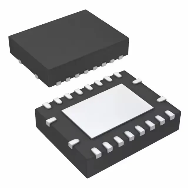
The 20-VQFN package with exposed pad (3.5x4.5 mm) needs a solid thermal via stitch under the pad if you're running near the 25 mA sink limit on multiple pins simultaneously; the pad also helps with mechanical stability in vibration-prone installations.
The PCF8574ARGYRG4 is the Tape & Reel variant of the base PCF8574A family; the base PCF8574 (without the 'A' suffix) is a different I²C slave address range, so check your address map before substituting.