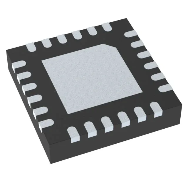
Texas Instruments PCA9555RGER — Interface & Transceivers

TI PCA9555RGER I²C I/O Expander, 16-bit, 400 kHz, 24-VQFN

MPNPCA9555RGER
Active

Texas Instruments PCA9555RGER, 16-bit I²C/SMBus I/O expander, 400 kHz clock, push-pull outputs, interrupt output, POR, 2.3V–5.5V supply, -40°C–85°C, 24-VQFN (4x4) exposed pad package.

$2.5200Ref. price · indicative, final on quote
Independent supplier — new & surplus stockAuthenticity-screened · ESD-safe packingListing updated Aug 2026

Specifications

PCA9555RGER specifications
ParameterValue
Output typePush-Pull
MountingSurface Mount
Voltage2.3V ~ 5.5V
Current - output source (Sink)10mA, 25mA
Frequency400 kHz
InterfaceI²C, SMBus
Operating temperature-40°C~85°C
PackageTape & Reel (TR); Cut Tape (CT)
FeaturesPOR
Number of i (O)16
Case24-VFQFN Exposed Pad
Interrupt outputYes

Product details

16-bit I²C I/O expander with interrupt and POR

The PCA9555RGER: It provides 16 push-pull I/O pins that can be individually configured as inputs or outputs, with a 400 kHz maximum clock frequency. An open-drain interrupt output (INT) signals the host when an input state changes, eliminating the need for constant polling. The integrated power-on reset (POR) ensures all I/O channels initialize to a known high-impedance state at startup, preventing uncontrolled output glitches during power sequencing. Each I/O can source 10 mA or sink 25 mA, sufficient for driving LEDs, relays, or small solenoids with external current-limiting resistors.

24-VQFN package — footprint and thermal notes

The PCA9555RGER is supplied in a 24-VFQFN exposed-pad package (supplier device package 24-VQFN, 4 mm × 4 mm body). The small footprint (4x4 mm) suits space-constrained designs, but.

I²C address configuration and bus loading

The PCA9555RGER uses three hardware address pins (A0, A1, A2) to set the I²C slave address, providing up to 32 possible addresses on the same bus (address range 0x20–0x27, plus the three address bits allow 8 addresses per device; multiple devices can share the bus if each has a unique address). At 400 kHz, the total bus capacitance (trace + device input capacitance) must stay under 400 pF to maintain signal integrity.

The base product number PCA9555 covers multiple package variants (including the RGER suffix for the 24-VQFN), so a PCN affecting one variant would typically apply across the family — worth monitoring if the design is long-lived.

Frequently asked questions

Is PCA9555RGER a direct replacement for PCA9555?

Yes, the PCA9555RGER is a direct replacement for the base PCA9555 in the 24-VQFN package. The 'RGER' suffix denotes the specific package option (24-VQFN with exposed pad). The electrical specifications — 16 I/O, I²C interface, 400 kHz clock, 2.3 V–5.5 V supply, interrupt output, POR — are identical across the PCA9555 family. If your existing design uses a different package (e.g., SOIC or TSSOP), the RGER variant is not footprint-compatible without a board layout change.

What is the I2C address range of PCA9555RGER?

The PCA9555RGER uses three address pins to set the I²C slave address. The base address is 0x20 (with all address pins tied low), and the three pins provide 8 possible addresses (0x20 through 0x27). By connecting the address pins to VCC, GND, or leaving them floating (some implementations), you can achieve up to 32 unique addresses on the same bus if multiple PCA9555 devices are used. The address is set at power-up and cannot be changed dynamically.