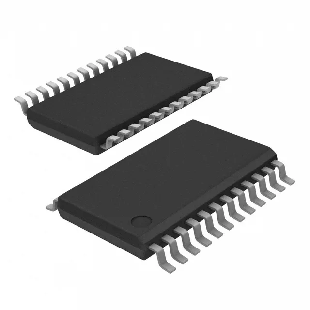
What this 16-bit I/O expander brings to the bus
It provides 16 push-pull outputs or inputs, configurable per bit through the I²C interface, with a power-on reset (POR) that initializes all I/O as inputs. Clock frequency tops out at 400 kHz, which is standard-mode I²C speed; the interrupt output (open-drain) flags the host when an input changes state, avoiding continuous polling. Output source/sink capability is 10 mA source and 25 mA sink per pin, enough to drive LEDs or small relays directly.
Supply voltage and logic-level compatibility
If your microcontroller runs at 3.3 V and the peripheral bus is 5 V tolerant, this part sits on either side without extra components. The I²C pins are 5 V tolerant even when VDD is 3.3 V, so a 5 V master can talk to it directly. The POR feature means the outputs come up as inputs (high-impedance) after power-on, which avoids unintended drive conflicts during startup — a common headache when a GPIO expander powers up before the host finishes reset.
I/O drive and interrupt handling
Each I/O pin can sink 25 mA or source 10 mA. That 25 mA sink is enough for a standard green LED with a 150 Ω resistor at 3.3 V, or a small signal relay coil with a flyback diode. The interrupt output (INT) is open-drain and asserts low when any input configured for interrupt changes state. This saves the host from polling the I²C bus — the interrupt line wakes the MCU only when something happens. The interrupt clears when the host reads the input port register via I²C.
The Tape & Reel (TR) packaging option is standard for automated pick-and-place assembly.