What the 100 kHz ceiling means for your timing design
The NE555PWR is a single 555-type timer/oscillator from Texas Instruments, specified for a maximum astable frequency of 100 kHz. That 100 kHz ceiling is set by the internal comparator propagation delays and the discharge transistor's saturation time — not by the external RC network alone. For a monostable pulse, the minimum output pulse width is roughly 10 µs; below that the timing capacitor doesn't charge to the threshold before the discharge cycle starts. Supply voltage range is 4.5 V to 16 V, and the quiescent supply current is 10 mA typical at 5 V. The wider the supply rail, the shorter the propagation delay through the comparators — so the 100 kHz ceiling is easier to reach at 15 V than at 5 V. If your design needs 200 kHz, this part won't get there; you'd step to a CMOS 555 like the TLC555, which runs to 2 MHz at a fraction of the supply current.
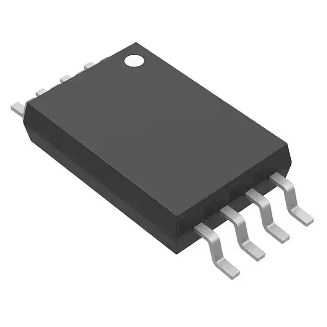
8-TSSOP footprint and board integration
That's a surface-mount package with a 1.1 mm seated height — it sits low enough for a 1.6 mm PCB to clear a 2 mm card guide. That covers benchtop, lab equipment, and indoor consumer gear. If the board sits in an unventilated enclosure near a power supply that hits 85 °C, this part drifts; the timing capacitor leakage doubles every 10 °C, and the threshold voltage shifts enough to pull the frequency off by several percent.
CT is for prototyping or low-volume builds.