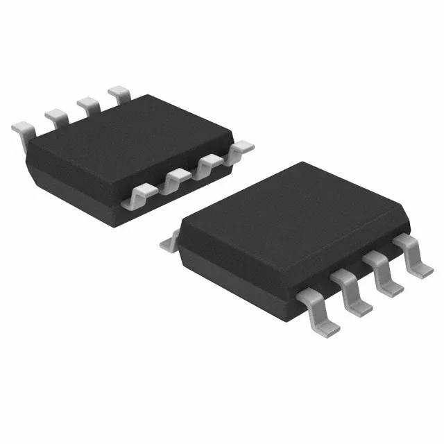
What the 100 kHz ceiling means for your timing circuit
The NE555PS is a single 555-type timer oscillator from Texas Instruments, rated for a maximum oscillation frequency of 100 kHz. In astable mode, the actual achievable frequency depends on the RC time constant and the propagation delay through the internal comparators — the 100 kHz figure is the upper bound before the output pulse width collapses. For a 50% duty cycle square wave at 100 kHz, the timing resistor and capacitor values must be chosen so that the RC charging time is at least several times the internal discharge time (about 0.3 µs typical) to avoid missing edges.
Supply voltage and current budget
The NE555PS operates from a 4.5 V to 16 V supply rail, drawing a quiescent supply current of 10 mA typical. At 5 V, the output high voltage is roughly 3.3 V into a 100 mA load — the output stage drops about 1.7 V from the rail. If the downstream logic requires a 3.3 V CMOS-compatible high level, a 5 V supply is marginal; a 12 V supply gives a clean 10.6 V high output that can drive a relay coil or a MOSFET gate directly through a current-limiting resistor.
Temperature grade and environment
The timing accuracy drifts with temperature — the 555's internal voltage divider and comparator offset shift by roughly 50 ppm/°C typical, so a 1 kHz oscillator at 25 °C may drift to 1.0035 kHz at 70 °C. For a 5% timing tolerance across the full range, the external RC components should be ±1% or better, and the timing capacitor should be a low-TC type like C0G/NP0.
A decoupling capacitor of 0.1 µF ceramic placed between pins 1 (GND) and 8 (VCC) within 5 mm of the package is recommended to suppress supply ripple that couples into the threshold and trigger comparators. The control voltage pin (pin 5) should be bypassed with a 0.01 µF capacitor to ground when not used, or tied to a stable reference voltage for duty-cycle modulation.