10 MHz GBW and 9 V/µs slew — what they mean for the signal chain
The NE5532P: For audio line-level signals (20 Hz–20 kHz), this is generous — the op-amp's open-loop gain stays well above 60 dB across the audio band, so distortion from loop-gain variation is negligible. The 9 V/µs slew rate defines the large-signal output swing before slew-induced distortion appears. Supply current is 8 mA per channel (16 mA total for the dual). That is moderate for a 10 MHz bipolar op-amp — about half what a faster part like the NE5534 draws, and a reasonable budget for a multi-channel audio mixer or active filter bank.
Dual-channel in a DIP-8 — board-fit and replacement logic
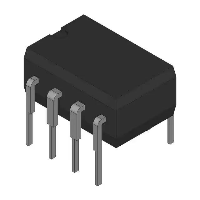
Two op-amps in one 8-pin DIP package (0.300-inch row spacing, 7.62 mm body width). The pinout is standard: pins 1–3 for channel A, pins 5–7 for channel B, pin 4 for V−, pin 8 for V+. Through-hole mounting means no reflow profile, no moisture sensitivity level (MSL) to track. The tube packaging keeps the leads straight and the bodies aligned — store the tube in an ESD-safe bin, not a dry cabinet. Hand-solder or wave-solder; the DIP footprint is the same as the LM358, TL072, or any standard dual op-amp in DIP-8. For an audio preamp in a studio rack or a signal-conditioning board in a lab instrument, it is fine. Do not spec it into an engine bay or an outdoor enclosure without a heater.
Supply rails and output drive — what the numbers allow
The 30 V maximum is the total across V+ and V−; exceeding it damages the input stage. For a ±15 V supply, the common-mode input range extends to about ±12 V, not rail-to-rail. Output current is 38 mA per channel typical. That drives a 600 Ω load to ±12 V swing, or a 32 Ω headphone to about 1.2 Vrms — enough for line-level outputs but not a speaker driver. The output stage is class AB with short-circuit protection; driving a capacitive load above 100 pF may cause ringing unless a small series resistor (50–100 Ω) is added. Input offset voltage is 500 µV typical, 4 mV maximum. For DC-coupled audio paths, the offset appears at the output multiplied by the noise gain — at a gain of 10, expect up to 40 mV DC at the output. If that matters, AC-couple the signal path or use a servo loop. Input bias current is 200 nA typical (bipolar input stage). With a 10 kΩ source impedance, the offset from bias current is 2 mV — comparable to the offset voltage itself. For source impedances above 50 kΩ, the bias current dominates the DC error; a JFET-input op-amp would be a better fit.
Active lifecycle and compliance — no last-time-buy pressure
ROHS3 compliant (no exemptions). No UL or IEC certification applies to a monolithic op-amp — the package is the only regulatory concern, and the DIP-8 is a decades-proven mold compound. No stock-holding claim — each RFQ is priced fresh.