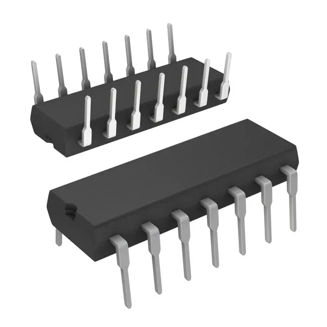
Dual 555 timer in a 14-pin DIP footprint
The NA556N: The through-hole PDIP package mates with standard breadboards, prototype boards, and legacy socket patterns — no board redesign needed if you are replacing a single-sourced dual timer on an existing BOM. Each timer section operates across a 4.5 V to 16 V supply rail, drawing 20 mA total for both halves. The -40°C to +105°C temperature range covers industrial enclosures, outdoor telecom cabinets, and under-hood automotive auxiliary circuits where the ambient stays below the 105°C ceiling.
Supply voltage flexibility and per-timer current budget
The 4.5 V minimum supply means the NA556N starts reliably from a 5 V rail with 0.5 V of headroom for ripple; the 16 V maximum lets it run on an unregulated 12 V battery bus without a pre-regulator. Each timer's output can sink or source 200 mA (typical), but the total 20 mA supply current is the quiescent draw — the load current comes from the supply rail, not the bias line, so the 20 mA figure is the chip's own consumption, not the output drive budget. At 20 mA total supply for two timers, the NA556N dissipates roughly 320 mW at 16 V — well within the 14-DIP's thermal capacity in still air. No heatsinking is needed for timing or pulse-generation duty below a few hundred hertz.
Active lifecycle and compliance documentation
The Tube packaging is the standard through-hole delivery format — 25 or 50 pieces per tube depending on the factory pack quantity. For BOM quantities that do not align with tube multiples, the part is quoted per the exact line-item count at RFQ.