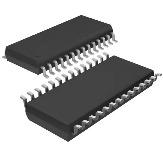
What this 16-bit MCU brings to a low-power design
The 16 MHz clock is the CPU's maximum operating frequency. At this speed, a single-cycle instruction executes in 62.5 ns, which sets the timing budget for interrupt latency and bit-banged protocols. The MSP430 architecture is pipelined, so most instructions complete in one clock cycle, giving an effective throughput close to 16 MIPS. For a UART at 115200 baud, the bit period is 8.68 µs — the CPU has about 139 clock cycles per bit to service the interrupt and shift data, which is comfortable. The internal oscillator is trimmed to ±1% accuracy over temperature, sufficient for asynchronous serial communication without an external resonator.
512 bytes of RAM — sizing the firmware stack
The 512 x 8 RAM (512 bytes) is the tightest resource on this MCU. It must hold the call stack, global variables, and any DMA or interrupt buffers. A typical I²C or SPI transaction buffer of 64 bytes consumes 12.5% of the RAM. If the application uses a real-time operating system, the kernel's task stacks will eat into this quickly — a lightweight cooperative scheduler with two tasks might need 100 to 150 bytes for context storage. For most single-loop sensor-read-and-transmit applications, 512 bytes is workable, but firmware must be written with static allocation and no dynamic malloc. The 16 KB Flash leaves plenty of room for lookup tables and constant data that stays in program memory.
Peripheral set: ADC, serial interfaces, and PWM
The MSP430G2533 integrates an 8-channel 10-bit ADC, which samples analog inputs like temperature sensors, potentiometers, or current-shunt voltages without an external converter. The serial interface block includes I²C, SPI, and UART — covering the three most common peripheral buses. IrDA and LINbus support are also listed, which is useful for infrared data links or automotive local-interconnect network nodes. The PWM output, combined with the watchdog timer and brown-out reset, makes this MCU suitable for motor-speed control or LED dimming in a simple closed-loop system. All 24 I/O pins are available on the 28-TSSOP package, which is a compact 4.4 mm wide body — good for space-constrained PCBs.
At 3.3 V, the MCU draws roughly 230 µA in active mode at 1 MHz and less than 1 µA in standby — the exact numbers depend on the clock divider and peripheral configuration, but the MSP430 family is known for sub-1 µA sleep currents.