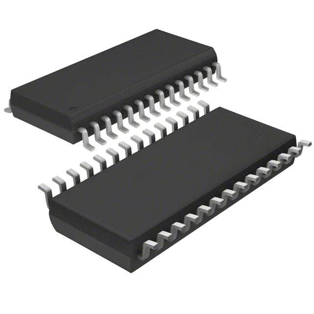
What this 16-bit MSP430 brings to a sensor or control board
On-chip peripherals include an 8-channel 10-bit ADC, brown-out detection, PWM, and a watchdog timer, plus serial connectivity covering I2C, SPI, UART, IrDA, and LINbus. The 28-TSSOP package (4.4 mm body width) fits space-constrained PCBs in industrial sensors, portable instruments, and automotive cabin modules.
At 16 MHz, the MSP430G2533 executes most single-cycle instructions, giving it a MIPS rating roughly equal to the clock speed. That is enough for reading a sensor via I2C or SPI at 100 kHz, updating a PWM output at 10 kHz, and running a simple control PID loop in the remaining cycles.
16 KB Flash and 512 B RAM — sizing the firmware budget
The 16 KB Flash (16K x 8) is the program storage. A typical sensor node firmware with ADC sampling, UART logging, and I2C communication fits in about 6–10 KB, leaving headroom for field-upgradeable bootloader code. The 512 bytes of RAM (512 x 8) is the tight constraint: it holds stack, global variables, and small buffers. A 256-byte UART receive buffer plus a 128-byte sensor data structure uses most of it, so any large lookup table or double-buffered DMA transfer needs to live in Flash and be copied to RAM only when needed.
That means it is still in volume production, no last-time-buy notice has been issued, and it remains a valid choice for new product introductions.