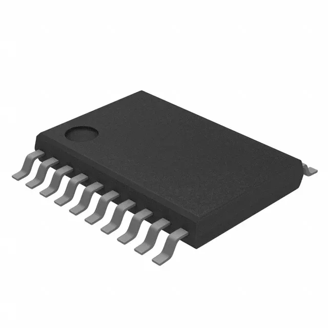
16 MHz ultra-low-power MCU for sensor and control applications
The 16 MHz clock rate is the ceiling for instruction throughput. At this speed the MSP430 CPU16 executes most single-cycle instructions, so a tight control loop reading the ADC, applying a PID correction, and updating a PWM duty cycle completes in under a few microseconds. Flash wait states are not an issue at 16 MHz — the part runs with zero wait states from Flash, so branch latency stays predictable.
Memory budget: 16 KB Flash, 512 B RAM
The 16 KB Flash (16 K × 8) holds firmware for a single-purpose sensor node or a modest control algorithm with a lookup table. The 512-byte RAM is the tight constraint: it limits the stack depth, the number of active buffers, and the size of data structures. A typical application reading one ADC channel and logging to serial can fit in under 128 bytes of RAM, but a multi-channel data logger with a circular buffer will bump against the ceiling. Plan the RAM budget before writing the ISR stack.
At 3.3 V the active-mode current draw is typically under 300 µA at 1 MHz, scaling linearly with clock frequency.
Package and footprint: 20-TSSOP
The 20-TSSOP (0.173" body width, 4.40 mm) is a compact surface-mount package with 0.65 mm pitch. The supplier device package is 20-TSSOP. The small footprint suits space-constrained designs, but the fine pitch demands careful soldering profile control and a clean PCB stencil.
It is ROHS3 compliant.