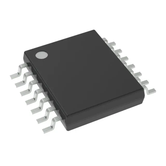
Typical applications include simple sensor interfaces, battery-powered control loops, and basic I/O expansion where the low pin count and small footprint keep the BOM tight.
16 MHz core and 4 KB Flash — sizing the firmware budget
The 16 MHz clock rate is typical for the MSP430G2xx series and suits event-driven polling or low-duty-cycle processing. The 4 KB Flash (4K x 8) is the program memory ceiling — enough for a small state machine, a few ADC readings, or a Modbus RTU slave node, but tight for a full protocol stack with OTA. The 256-byte RAM (256 x 8) limits data buffers and stack depth; watch the linker map if you are adding a printf or a large lookup table.
On-chip peripherals include I²C, SPI, and USI for serial communication, plus PWM, WDT, and DMA for control and housekeeping tasks. With 10 general-purpose I/O pins in the 14-TSSOP package, you get enough for a few sensor inputs, an LED driver, and a serial link — but plan the pin allocation before layout because the USI module shares pins with the GPIO bank.
The 14-TSSOP (0.173" body width, 4.40 mm) is a fine-pitch surface-mount package. The supplier device package is 14-TSSOP. Standard reflow profiles work; The 0.65 mm pin pitch needs a careful solder-paste stencil aperture to avoid bridging.
The base product number is MSP430G2312; the IPW14 suffix denotes the 14-TSSOP package and industrial temperature grade.