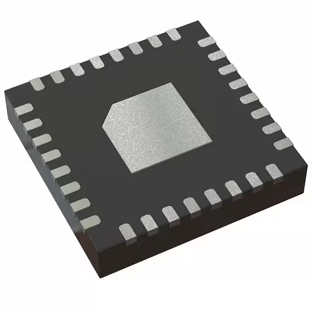
16 MHz, 2 KB Flash, 256 B RAM — the low-power control tier
With 24 general-purpose I/O lines, an 8-channel 10-bit ADC, and serial interfaces including I²C, SPI, and UART, this part covers the typical peripheral set for a low-pin-count mixed-signal controller.
256 bytes of RAM — sizing the stack and buffers
The 256 x 8 RAM allocation is the tightest constraint for firmware. A typical interrupt service routine with a few local variables can consume 20–40 bytes of stack; a UART receive buffer of 64 bytes leaves about 150 bytes for the main loop's working set. This part is not suited for large data arrays, TCP/IP stacks, or multi-level state machines with deep call trees. It fits best in applications where the firmware fits in a few hundred bytes of code and uses register-based or single-buffer I/O.
TI has not issued a last-time-buy notice or end-of-life notification for this device as of the current record.
Package and thermal pad — what the layout sees
The exposed pad also serves as the ground return for the core and I/O — the layout should connect it to the ground plane with multiple vias to keep the inductance low.