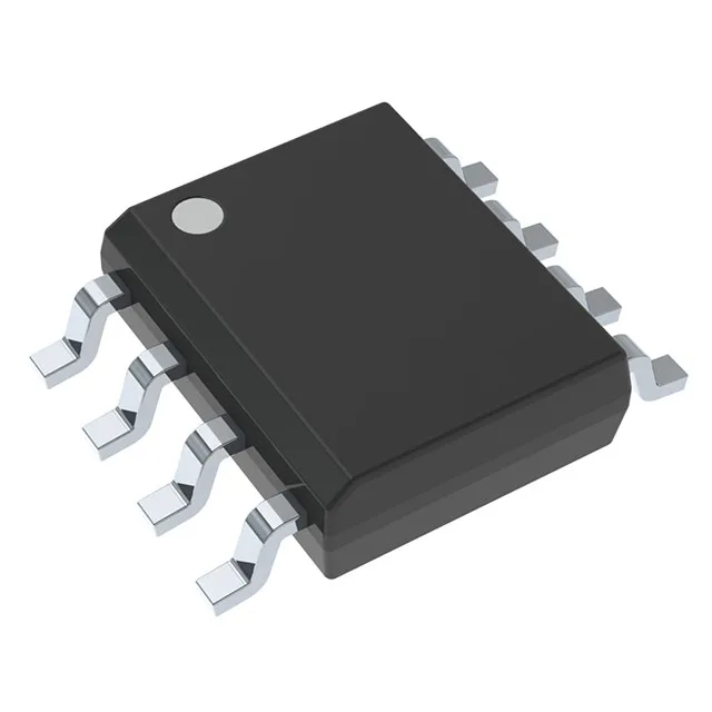
Active production — no bootloader flash tax here
The MSP430G2230IDR: The 2 KB (2K x 8 + 256B) on-chip FLASH is all yours — the MSP430 boot ROM lives in a separate memory region, so none of the advertised program space is eaten by a factory bootloader. What you see in the memory map is what you get for application code.
What the 16MHz core and 128B RAM mean for firmware fit
The 16-bit MSP430 CPU16 core runs at 16 MHz — this is the maximum system clock, not a turbo mode. With 128 x 8 bytes of RAM, the firmware budget is tight: a typical HAL plus a minimal scheduler leaves about 80 bytes for stack and global variables. Plan the call tree depth and interrupt nesting before you start coding. Four I/O pins in an 8-SOIC package — every pin carries a secondary function (USI for I²C/SPI, or ADC input). The pin mux is shared, so a single design decision (e.g. using the USI for SPI) permanently locks out the ADC on those same pins. Read the port map in the datasheet before laying out the board. The internal oscillator (DCO) is calibrated at factory to ±1% over temperature — no external crystal needed for UART or SPI bit-banging at moderate baud rates. Brown-out detect and reset (BOR) are built in, so a simple RC on the RST pin is sufficient for most low-noise environments.
Package and footprint note
Tape & Reel packaging (2,500 units per reel) is the standard ordering option.