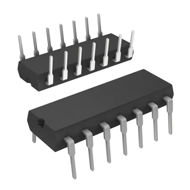
16 MHz MSP430 core in a through-hole DIP — the firmware budget and the pin count
The MSP430G2131IN14: The 14-pin DIP package (0.300" row spacing) gives you 10 general-purpose I/O lines. That pin count is the hard limit on external connections — every peripheral, sensor interrupt, or LED driver competes for those 10 pins. The internal peripherals (Brown-out Detect/Reset, POR, PWM, WDT) are wired to dedicated pins, so the usable I/O count is effectively 8–10 depending on the oscillator and reset configuration. On-chip data converters include an 8-channel, 10-bit ADC — enough for reading multiple analog sensors (thermistor, potentiometer, current shunt) without an external mux.
The internal oscillator is trimmed to ±1% accuracy at 25°C, which is sufficient for UART communication at 9600 baud without an external resonator. For applications that need tighter timing (e.g., I²C at 400 kHz), the clock source can be switched to an external crystal on the XIN/XOUT pins, though that consumes two of the 10 I/O lines.
Active lifecycle and through-hole availability
The 14-pin DIP package is a through-hole form factor — it breadboard-prototypes easily and is preferred for low-volume production or field-repairable assemblies where a socket is used. The same die is also available in a surface-mount TSSOP-14 package as the MSP430G2132IPW14R, which shares the same 1 KB Flash, 128 B RAM, and 10-bit ADC but uses a different pinout (the TSSOP adds a VREF+ pin).