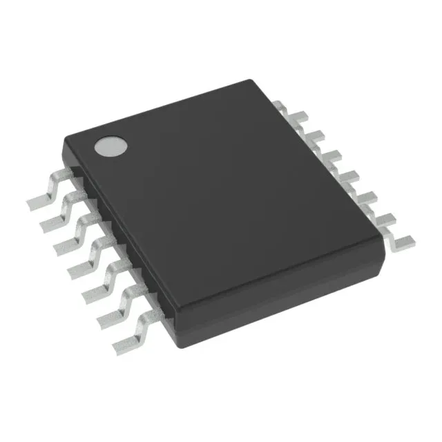
16MHz MSP430 core with 1KB flash — what the memory budget means for the BOM
The MSP430G2121IPW14 is a 16-bit MCU from TI's MSP430G2xx value line, clocked at 16 MHz with 1 KB of on-chip flash and 128 bytes of RAM. That memory ceiling defines the firmware scope: a simple sensor poll-and-transmit loop, a single control-law state machine, or a small bootloader fit within 1 KB, but a protocol stack or data logger will overflow it. The 128 x 8 RAM (128 bytes) is the active variable and stack space — enough for a few 16-bit counters and a small buffer, but tight for any buffered I/O or multi-layer function calls. Budget the stack depth during interrupt service routines; a deep call tree will push past the limit.
Supply range and temperature grade — deployment envelope
For applications needing precise timing or a lower-power sleep clock, an external 32 kHz watch crystal can be connected to the dedicated LFXT1 pins (not all pins are brought out on the 14-pin package — verify the pinout against the application note).
On-chip peripherals and I/O — what is included and what is not
The integrated peripheral set includes brown-out detect (BOD), power-on reset (POR), a PWM timer, and a watchdog timer (WDT). These reduce external supervisory ICs and reset generators — the BOD monitors the supply rail and holds the MCU in reset below the threshold, which is critical for battery-powered designs where the voltage sags under load. Connectivity is limited to I²C and SPI via the universal serial interface (USI) module — no UART, no CAN, no LIN. The 10 GPIOs (on the 14-TSSOP package) must serve all external interfaces: if the design needs a UART, it must be bit-banged on two GPIOs, consuming pins and CPU cycles. Verify the BOM pin count against the 10 available I/O before committing the layout.
Package and board-fit — 14-TSSOP footprint
The 0.65 mm pitch is manageable on a two-layer board with proper trace width/spacing — no need for a four-layer stack-up just for fan-out. The supplier device package is 14-TSSOP; the footprint matches the standard JEDEC MO-153 variation.
The part is ROHS3 compliant (EU 2015/863), which covers the full ten restricted substances including the four phthalates.