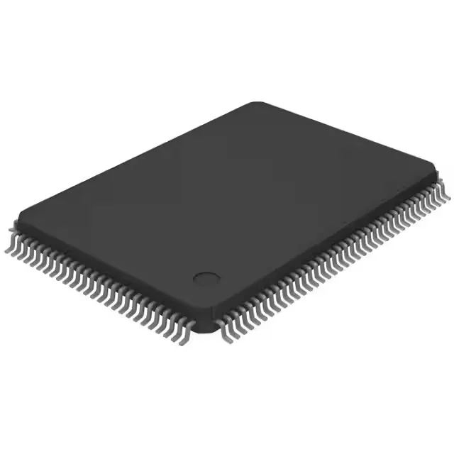
MSP430F67791IPEUR TI 16-bit Metering MCU, 512KB Flash, 128-LQFP
Texas Instruments MSP430F6xx series, 16-bit metering MCU, 512KB flash, 32KB RAM, 25MHz MSP430 CPUXV2, 90 I/O, 8x10b A/D plus 7x24b sigma-delta, 1.8–3.6V supply, -40°C to 85°C, 128-LQFP (20x14mm) in TR/CT packaging.
Specifications
| Parameter | Value |
|---|---|
| Series | MSP430F6xx |
| Mounting | Surface Mount |
| Oscillator type | Internal |
| Program memory type | FLASH |
| Voltage - supply (Vcc (Vdd)) | 1.8V ~ 3.6V |
| Operating temperature | -40°C~85°C(TA) |
| Speed | 25MHz |
| Package | Tape & Reel (TR); Cut Tape (CT) |
| RAM size | 32K x 8 |
| Core size | 16-Bit |
| Peripherals | Brown-out Detect/Reset, DMA, LCD, POR, PWM, WDT, 7x24b Sigma Delta Converter |
| Connectivity | I²C, IrDA, LINbus, SPI, UART/USART |
| Number of i (O) | 90 |
| Core processor | MSP430 CPUXV2 |
| Case | 128-LQFP |
| Data converters | A/D 8x10b |
| Program memory size | 512KB (512K x 8) |
Frequently asked questions
What supply voltage and current draw should I plan for the LDO and decoupling?
The MSP430F67791IPEUR operates from 1.8V to 3.6V. The internal oscillator drives the 25MHz core clock without an external crystal, so the supply rail sees burst current during sigma-delta sampling bursts. TI's standard MSP430 decoupling guideline is a 0.1µF ceramic per VCC pin under the package plus a bulk 4.7µF cap — the brown-out reset threshold is below 1.8V, so keep supply droop above that level under peak peripheral loading.
How many analog input pins does the 8x10b ADC use versus the 7×24b sigma-delta channels?
The 8×10-bit SAR ADC and the 7×24-bit sigma-delta converter are separate on-chip peripherals. The 128-LQFP package routes 90 I/O pins total; the sigma-delta inputs consume six pins for the three voltage and three current channels per phase, and the SAR ADC uses a subset of the remaining analog-capable pins for housekeeping measurements. Pin-sharing between the two converters is die-level fixed and the specific routing within the 128-LQFP pinout requires the TI datasheet pinout diagram to confirm which physical pins map to each function. Submit an RFQ to request the full pinout documentation.