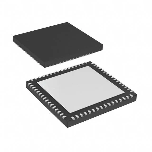
The MSP430F5227IRGCT is a 16-bit MCU from the MSP430F5xx family, built around the CPUXV2 core clocked at 25 MHz. That clock rate, combined with the 16-bit RISC architecture, delivers enough throughput for sensor-fusion loops running at a few kilohertz — think a battery-powered environmental monitor that reads a humidity sensor, runs a compensation algorithm, and logs data over I²C every 100 ms. On-chip memory is 64 KB of flash and 8 KB of RAM. The flash holds the application code and calibration tables; the 8 KB RAM leaves room for a modest protocol stack (say a stripped I²C slave or UART command parser) plus a few hundred bytes of working variables. 31 I/O pins are available in the 64-VQFN package. That covers a 16×2 character LCD, a 12-key matrix, three UARTs, and a handful of GPIOs for status LEDs and pushbuttons — typical for a handheld data-logger or a simple HMI panel.
Supply voltage and on-chip peripherals
The internal brown-out detect (BOD) monitors the rail and holds the core in reset if the supply dips below the threshold — no external supervisor needed for basic power-fail handling. Peripherals include a 12-channel 10-bit ADC, two 16-bit timers with PWM, a DMA controller, and a watchdog timer. The ADC is adequate for battery voltage monitoring, thermistor inputs, and current-sense feedback at sample rates up to 200 ksps. The DMA can move ADC results directly to RAM without CPU intervention — useful for keeping the core asleep between samples. Connectivity options are I²C, SPI, UART/USART, and IrDA. The I²C and SPI modules support multi-master and high-speed modes (up to 400 kHz for I²C, up to 8 MHz for SPI). The UART includes hardware flow control and IrDA encoding — handy for wireless IR data links in handheld terminals.
Sourced through authorized and independent distribution channels. No stock-holding claim — each order is sourced per the buyer's volume and delivery window.