16 MHz core — clock-tree and wait-state planning
The MSP430 CPU16 core runs at 16 MHz. At this speed the internal flash needs zero wait states up to about 8 MHz; above that, one wait state is required or the first instruction fetch after a branch will hard-fault. Plan the clock tree accordingly if you push the DCO or an external oscillator to the full 16 MHz.
60 KB Flash and 2.5 KB RAM — firmware and data budget
Program memory is 60 KB of FLASH (60K x 8 plus 256 bytes of information memory). RAM is 2.5K x 8. That Flash budget fits a moderate sensor-fusion or LCD-driven control loop; the RAM is tight for large frame buffers, so offload data to the Flash information memory or an external serial EEPROM over I²C or SPI.
On-chip peripherals include a brown-out reset, power-on reset, LCD driver (up to 160 segments), PWM timer, and watchdog timer.
72 I/O and 4x16-bit ADC — sensor interface capacity
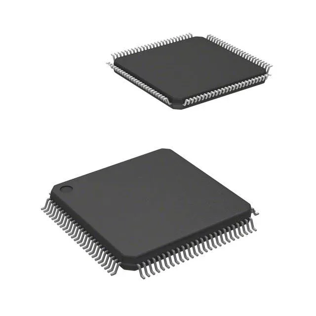
With 72 general-purpose I/O pins and a 4-channel 16-bit sigma-delta ADC, this part can handle multiple analog sensors alongside a segmented LCD display. The 100-LQFP (14x14 mm) package gives enough breakout for a mixed-signal board without resorting to a finer-pitch BGA.