What this 16-bit MCU brings to a mixed-signal sensor node
The on-chip LCD driver and DMA controller let it refresh a segmented LCD without stealing CPU cycles, which is why this part shows up in utility meters, portable medical monitors, and industrial panel indicators. The 80 general-purpose I/O lines give plenty of headroom for keypad scanning, external sensor interrupts, and parallel LCD data buses.
Memory and peripheral budget — what fits, what doesn't
92 KB of Flash is generous for a 16-bit ultra-low-power MCU. A typical firmware image with a real-time operating system, a Modbus RTU stack, and a segmented LCD driver fits in about 48–64 KB, leaving room for field-upgrade staging. The 8 KB RAM is the tighter resource: a 128×64 pixel frame buffer at 1 bpp takes 1 KB, and a moderate-size sensor data log at 2-byte samples eats the rest quickly. Plan to use the DMA for block transfers to the LCD controller to keep the CPU free for math. The integrated peripherals — brown-out detect, POR, PWM, and watchdog — reduce external BOM count. The brown-out reset is critical for battery-powered designs where a dying cell could corrupt the Flash write sequence.
8 MHz is the core speed, not the peripheral clock. The internal oscillator means no external crystal is needed for the CPU, but the UART baud-rate generator and the PWM timer resolution depend on the same clock tree. At 8 MHz, a 16-bit timer gives you 8.192 ms before overflow at 1:1 prescale — fine for a 100 Hz sensor readout, but you'll need a prescaler or a second timer for a 1-second heartbeat. The SCI and UART modules can generate standard baud rates up to 115200 without issue.
Package and temperature grade — board-level fit
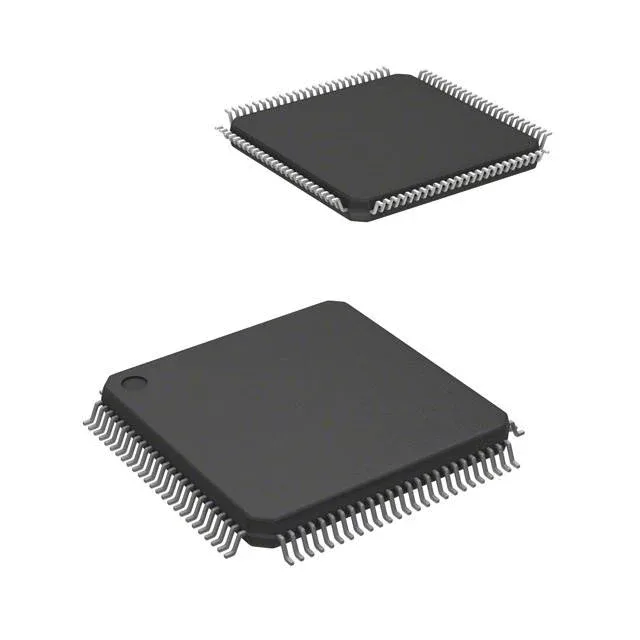
Housed in a 100-pin LQFP with a 14×14 mm body (0.5 mm pitch), it's a standard QFP footprint that routes easily on a two-layer board.