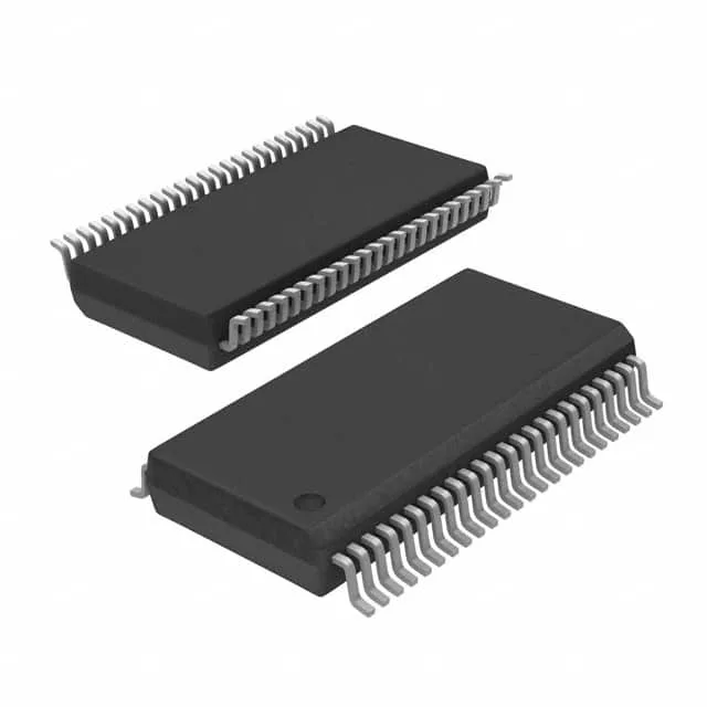
Mixed-signal MCU with LCD drive and on-chip converters
It integrates 16 KB of Flash program memory, 256 x 8 bytes of RAM, a 16-bit ADC, a 12-bit DAC, and a segment LCD driver — a combination that suits metering, sensor conditioning, and human-machine interface panels where a separate display controller and external analog front-end would otherwise inflate the BOM.
8 MHz core — enough for slow sensor loops and display refresh
The 8 MHz clock rate is modest by today's MCU standards, but it is deliberate: the MSP430 architecture is designed for ultralow-power active and sleep modes. At 8 MHz the core can service a 16-bit ADC conversion, update an LCD segment, and run a PID loop with margin.
16 KB Flash and 256 B RAM — sizing the firmware budget
With 16 KB of Flash and 256 bytes of RAM, this part is not a candidate for complex RTOS stacks or large data buffers. It fits firmware that fits in 8–12 KB of compiled code — a Modbus slave, a flow-meter algorithm, a thermostat state machine — leaving headroom for a bootloader and calibration constants. The 256 B RAM is the tighter constraint: any significant data logging or large lookup table pushes the design to an external serial EEPROM or a larger MSP430 sibling.
Peripheral set: LCD, ADC, DAC, and supervisory blocks
The integrated LCD driver can directly drive a segmented glass display without an external driver IC — a cost and board-area win for gas-pump readouts, utility meters, or medical-device panels. The 16-bit ADC provides enough resolution for precision sensor measurements (thermocouple, strain gauge, pressure transducer), and the 12-bit DAC can generate an analog setpoint or drive an external actuator. The brown-out detect and POR eliminate external reset supervisor ICs in most designs.