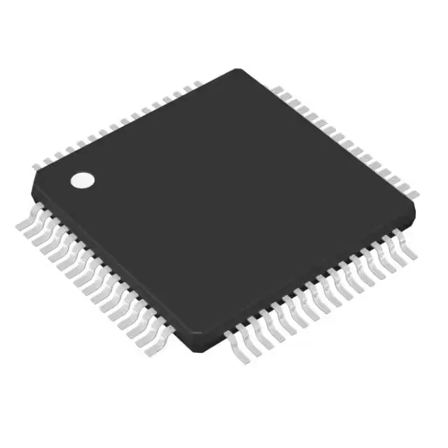
Texas Instruments MSP430F412IPM — Microcontrollers & Processors (MCU / MPU / DSP)

Texas Instruments MSP430F412IPM 16-bit MCU, 8 MHz

MPNMSP430F412IPM
Active

Texas Instruments MSP430x4xx series MSP430F412IPM, 16-Bit Microcontroller, MSP430 CPU16 core, 8MHz, 4KB (4K x 8 + 256B) FLASH, 256 x 8 RAM, 48 I/O, Slope A/D, 64-LQFP, -40°C to 85°C.

$4.7200Ref. price · indicative, final on quote
Independent supplier — new & surplus stockAuthenticity-screened · ESD-safe packingListing updated Aug 2026

Specifications

MSP430F412IPM specifications
ParameterValue
SeriesMSP430x4xx
MountingSurface Mount
Oscillator typeInternal
Program memory typeFLASH
Voltage - supply (Vcc (Vdd))1.8V ~ 3.6V
Operating temperature-40°C~85°C(TA)
Speed8MHz
PackageTray
RAM size256 x 8
Core size16-Bit
PeripheralsBrown-out Detect/Reset, LCD, POR, PWM, WDT
Number of i (O)48
Core processorMSP430 CPU16
Case64-LQFP
Data convertersSlope A/D
Program memory size4KB (4K x 8 + 256B)

Product details

16-bit MCU with integrated LCD driver — what the 4 KB Flash and 256 B RAM mean for your firmware budget

The MSP430F412IPM: The 256 B RAM limits stack depth and buffer count. The integrated LCD driver eliminates a separate display driver IC.

The internal oscillator (no external crystal needed for the core clock) reduces BOM count, though the 8 MHz accuracy is adequate for UART baud-rate generation and timer-based PWM, not precision timekeeping.

64-pin LQFP — routing the 48 I/O and LCD segments

The package pitch is 0.5 mm, typical for a 64-pin LQFP, so a 4-layer board with a ground plane under the MCU is recommended for reliable routing of the LCD segment lines and the 48 I/O. The 48 I/O count is enough to drive a 7-segment x 6-digit LCD plus a few pushbuttons and a buzzer, but it leaves no spare pins for an external parallel memory or a wide sensor bus without a port expander.

Frequently asked questions

What is the difference between MSP430F412IPM and MSP430F413IPM?

The MSP430F413IPM is a higher-density sibling in the same MSP430x4xx family and the same 64-LQFP package. The key difference is program memory: the MSP430F412IPM has 4 KB of Flash, while the MSP430F413IPM carries 8 KB of Flash. Both parts share the same 256 x 8 RAM, 48 I/O, LCD driver, and peripheral set. If your firmware fits in 4 KB, the MSP430F412IPM is the cost-optimized choice; if you need the extra 4 KB for a larger display map or additional control logic, the MSP430F413IPM is the direct upgrade without a board respin.

What tools are needed to program the MSP430F412IPM?

Programming and debugging the MSP430F412IPM requires a TI MSP430 Flash emulation tool (FET) such as the MSP-FET430UIF or the newer MSP-FET. The debug interface is the standard 4-wire JTAG (TMS, TCK, TDI, TDO) or the 2-wire Spy-Bi-Wire (SBW) mode. The IDE can be TI's Code Composer Studio (CCS) or IAR Embedded Workbench for MSP430. The target board needs a 14-pin JTAG header (TI's standard 2x7 connector) or a 4-pin SBW header for programming.