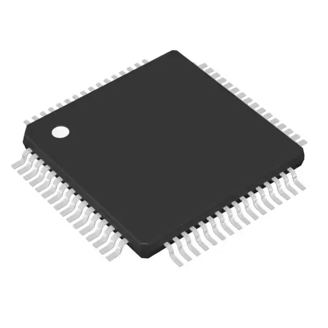
The MSP430F2619TPMR: It runs at 16 MHz and carries 120 KB of Flash program memory plus 4K x 8 of RAM, with 48 general-purpose I/O lines. The internal oscillator keeps the external BOM lean for many applications.
The 16 MHz clock is the maximum CPU speed for this core. At that frequency the Flash controller may need a wait state inserted for zero-wait access; the datasheet's timing tables specify the required configuration. The 16 MHz limit sets the throughput ceiling for the ADC sampling rate and the PWM timer resolution. For applications that need deterministic interrupt latency or tight loop execution, the 16 MHz clock with the single-cycle multiplier keeps context-switch overhead low.
120 KB Flash and 4K x 8 RAM — sizing the firmware
The 120 KB Flash (organized as 120K x 8 plus a separate 256-byte information memory) is enough for a real-time control stack, a bootloader, and moderate application code. The 4K x 8 RAM (4 KB) is the working memory; it holds stack, global variables, and DMA buffers. Designs that stream ADC data or run a small RTOS should budget RAM usage carefully — the 4 KB ceiling is the constraint, not the Flash. The information memory (256 bytes) is typically used for calibration constants or unique device IDs that survive a mass erase.
It is ROHS3 compliant.