Active production — no last-time-buy clock ticking
The MSP430F2252IDAR: For a BOM line carrying this order code, the supply risk is minimal: no looming phase-out, no forced migration to a successor.
16 MHz CPU — real-time loop ceiling
The MSP430 CPU16 core runs at 16 MHz. That clock sets the instruction throughput for control loops, sensor polling, and communication framing — a 16-bit RISC architecture with a single-cycle multiply, so tight timing tasks like PWM updates or UART bit-banging fit within the cycle budget. The 16 KB flash and 512 B RAM define the firmware footprint ceiling. For a typical sensor-node application running a scheduler, a few communication stacks, and a 10-bit ADC service routine, expect ~60-70% flash utilization before the linker starts complaining. The 512 B RAM is tight — global variables, stack, and a modest buffer pool must be budgeted early in firmware design.
Peripheral set — sensor-network ready
Connectivity covers I²C, SPI, UART/USART, IrDA, and LINbus. That is the standard mix for industrial sensor buses (I²C for local ADC/DAC, SPI for external memory or radio, UART for Modbus RTU or debug console). LINbus is a bonus for automotive-adjacent subnets. The 12-channel 10-bit ADC handles multi-point analog sensing — temperature, pressure, current shunt — without an external mux. The 32 GPIO give enough pins for a parallel LCD bus, keypad matrix, or a bank of discrete outputs alongside the serial interfaces. Brown-out detect and POR mean the MCU resets cleanly on power-up and brown-out without an external supervisor IC. The watchdog timer catches firmware hangs — a standard requirement for unattended or safety-related equipment.
Package and supply — board-fit checklist
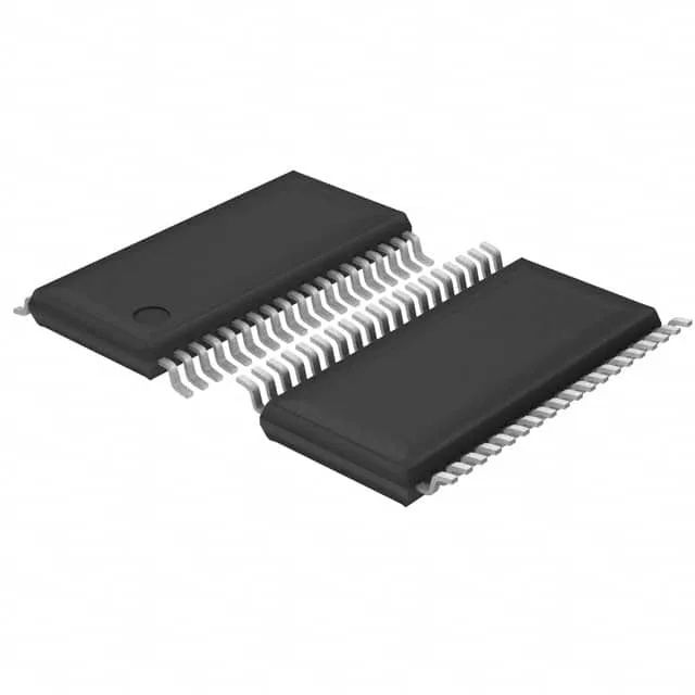
38-TSSOP with 0.65 mm pitch — a fine-pitch SMD package that needs a controlled reflow profile (peak 260°C, ramp rate ≤3°C/s) and X-ray inspection to verify hidden solder joints. The 6.10 mm body width fits a standard 0.100-inch grid layout. A 3.3 V rail from a buck or LDO powers the core and I/O directly; at 1.8 V the MCU draws less current but the flash access time lengthens, so the effective throughput drops. The internal oscillator eliminates an external crystal for non-precision timing — saves two pins and a board layer.