What this 16-bit MCU brings to a control-loop design
8 KB Flash and 512 bytes RAM — sizing the firmware budget
The 8 KB Flash (8K x 8 plus 256 bytes) and 512 x 8 RAM set a firm ceiling on code and data. This part suits applications where the control loop fits in a few kilobytes — think a PID regulator with a simple state machine, or a Modbus slave node. The 256 extra bytes in the Flash are typically reserved for calibration constants or unique device IDs. If your firmware already exceeds 6 KB, you are tight on headroom for field updates; consider the higher-density siblings in the MSP430F2xx series.
At 16 MHz the CPU16 core executes most instructions in one or two clock cycles, giving roughly 8-16 MIPS throughput. That is enough for 10 kHz control loops with a few ADC conversions per cycle, or for bit-banging a custom protocol at 1 Mbps.
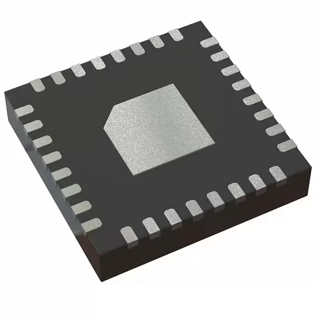
The 32-VFQFN with exposed pad (5x5 mm body) demands a good thermal via stitch under the paddle if you plan to run the core near 16 MHz at 105°C — the package relies on the PCB copper to pull heat out. For rework, the QFN is manageable with hot air if you pre-bake the board (MSL 3) and use a fine tip on the ground pad.
Peripherals and connectivity for mixed-signal control
The 8-channel 10-bit ADC covers analog inputs like thermistors, potentiometers, or current-sense resistors. For serial communication, the I²C, SPI, and UART blocks share pins with the LINbus and IrDA modes, so you can talk to a CO2 sensor, a CAN transceiver, or an infrared link from the same set of pads.